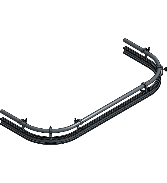
ShowTrack
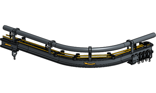
Rope Operated Curved
Installation Manual
Installation Manual
No part of this publication may be duplicated or edited in any form or by any means, including any type of electronic or mechanical method without prior written permission from ShowTex.
ShowTex and its employees are fully aware of their task to provide a reliable edition of this document. Nevertheless, they cannot accept any form of liability for the direct or indirect consequences of imperfections that might remain in this edition. The material in this manual is subject to change without notice.
ShowTex warrants that its mechanical and technical products, when delivered in new condition, in original packing, sold directly and used in normal conditions are free from any defects in manufacturing, materials and workmanship. For more information about your local warranty terms, please check our website or contact your local ShowTex office.
All products from the ShowTex Rental range are supposed to be returned in the same state as they were rented. Please treat our products with care, allowing the next user to enjoy the products as much as you did. The rented products are internally checked according to the general rental conditions. Be sure to check our rental guidelines on our website before installing and using this product: ShowTex rental guidelines
Read and understand this user manual before installing and or operating the system. Failure to follow the instructions in this document could result in serious injury!
Following the guidelines of this manual will reduce the risk of damaging the equipment or injuring yourself and the people around you. Nevertheless, ShowTex cannot be held accountable for any use or misuse of the equipment and supplies.
Damage to the system caused by any other method of installation than the one shown in this manual can only be repaired or fixed at the customer’s expense.
As a result of the above warning, any ShowTex product must be installed and operated by a qualified technician who knows its capabilities as well as its limitations.
In case you are uncertain about the eligibility of any hardware in your product, please get in touch with your local ShowTex office to receive additional guidance.
Thank you for choosing for ShowTex and purchasing one of our products. We want to ensure that your experience is as smooth and safe as possible, so we kindly request that you take a few moments to carefully read this manual before installing your new system.
This manual contains important information that will help you comply with health and safety regulations, as well as provide guidance on how to safely install, operate and maintain your product. Our team has taken great care to ensure that this manual is easy to understand and follow, using straightforward language and clear illustrations.
If you have any questions or concerns regarding the installation or use of your product, please feel free to contact your local ShowTex office. Our knowledgeable team members are always available to assist you and answer any questions you may have.
| Article number | Colour | Weight |
|---|---|---|
| 8075 0001 6007 | Black | 3.24 kg |
| Article number | Colour | Weight |
|---|---|---|
| 8075 0007 1007 | Black | 5.09 kg |
| Article number | Colour | Weight |
|---|---|---|
| 8075 0042 1807 | Black | 0.74 kg |
| Article number | Colour | Weight |
|---|---|---|
| 8075 0696 1207 | Black | 0.29 kg |
| Article number | Colour | Weight |
|---|---|---|
| 8075 0050 0007 | Black | 0.27 kg |
| Article number | Colour | Weight |
|---|---|---|
| 8075 0053 0007 | Black | 0.14 kg |
| Article number | Colour | Weight | WLL | SF |
|---|---|---|---|---|
| 8075 0680 0007 | Black | 0.89 kg | 60.00 kg | 2:1 |
| Article number | Colour | Weight | WLL | SF |
|---|---|---|---|---|
| 8075 0110 0007 | Black | 0.14 kg | 350.00 kg | 2:1 |
| Article number | Colour | Weight | WLL | SF |
|---|---|---|---|---|
| 8075 0690 0607 | Black | 0.37 kg | 150.00 kg | 2:1 |
| Article number | Colour | Weight | WLL | SF |
|---|---|---|---|---|
| 8075 0550 0007 | Black | 0.96 kg | 450.00 kg | 2:1 |
| Article number | Colour | Weight |
|---|---|---|
| 8070 0209 0257 | Black | 0.28 kg |
| Article number | Colour | Weight |
|---|---|---|
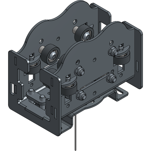
| 8070 0510 0507 | Black | 1.24 kg |
| Article number | Colour | Weight |
|---|---|---|
| 8070 0510 1007 | Black | 2.96 kg |
| Article number | Colour | Weight |
|---|---|---|
| 8070 0230 0507 | Black | 0.85 kg |
| Article number | Colour | Weight |
|---|---|---|
| 8070 0230 1037 | Black | 2.32 kg |
| Article number | Colour | Weight |
|---|---|---|
| 8075 0230 3507 | Black | 3.70 kg |
| Article number | Colour | Weight |
|---|---|---|
| 8070 0230 1067 | Black | 3.70 kg |
| Article number | Colour | Weight |
|---|---|---|
| 8070 0230 3537 | Black | 3.70 kg |
| Article number | Colour | Weight |
|---|---|---|
| 8700 0699 0037 | Black | 3.40 kg |
| Article number | Colour | Weight |
|---|---|---|
| 8070 0235 0507 | Black | 0.98 kg |
| Article number | Colour | Weight |
|---|---|---|
| 8070 0241 0007 | Black | 0.60 kg |
| Article number | Colour | Weight |
|---|---|---|
| 8070 0241 0017 | Black | 0.69 kg |
| Article number | Colour | Weight |
|---|---|---|
| 8075 0400 0017 | Black | 0.54 kg |
| Article number | Colour | Weight |
|---|---|---|
| 8075 0410 0017 | Black | 0.48 kg |
| Article number | Colour | Weight |
|---|---|---|
| 8075 0400 0027 | Black | 1.38 kg |
| Article number | Colour | Weight |
|---|---|---|
| 8075 0410 0027 | Black | 1.38 kg |
| Article number | Colour | Weight |
|---|---|---|
| 8075 0520 0007 | Black | 1.73 kg |
| Article number | Colour | Weight |
|---|---|---|
| 8075 0523 0007 | Black | 1.22 kg |
| Article number | Colour | Weight |
|---|---|---|
| 8075 0694 0007 | Black | 0.27 kg |
| Article number | Colour | Weight |
|---|---|---|
| 8075 0500 0007 | Black | 0.46 kg |
| Article number | Colour | Weight |
|---|---|---|
| 8075 0770 0017 | Black | 0.23 kg |
| Article number | Colour | Weight |
|---|---|---|
| 7530 0308 1007 | Black | 0.04 kg |

| Article number | Colour | Weight |
|---|---|---|
| 8050 0415 0077 | Black | 5.50 kg |
| 8050 0415 0097 | Black | 10.50 kg |
| Article number | Colour | Weight |
|---|---|---|
| 8050 0420 0007 | Black | 3.38 kg |
| Article number | Colour | Weight |
|---|---|---|
| 8050 0425 0107 | Black | 6.54 kg |
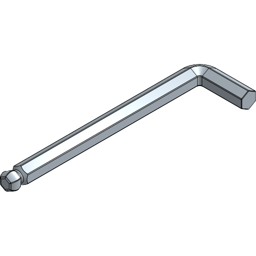
Throughout the manual, nearly all bolts will need to be tightened with an allen key 6.
An allen key 5 will be needed to tighten the screws of the Rope Clamps of the Master Carriers.
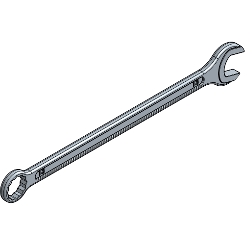
A wrench 17 will be needed to hold the nuts of the Overlap Arms in a Single Track setup.
Determine the number of suspension points you need, and calculate the distance between them by following the steps in this chapter.
Never exceed the maximum distance of 300 cm between each suspension point. But be cautious! The distance between suspension points also gets determined by the load on your track. Be sure to check the Load Capacity of the Track chapter in the Technical Data Sheet.
When connecting two rails, always have a suspension point within 50 cm of the connection.
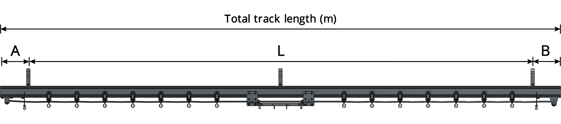
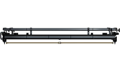
Determine the length of the track (L).
L = Total track length - A - B
Determine the number of suspension points (SP). If the number you become is a decimal number, round up.
Determine the distance between suspension points (D).
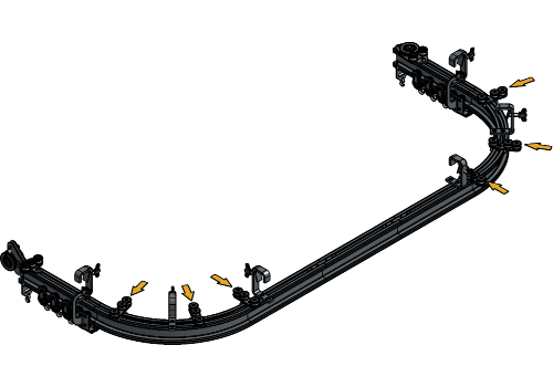
The rail mustn’t hang free at the end of the track, the first and last suspension point needs to be within 25 cm of the end of the track. This results in A and B having a maximum of 0,25 in the formula. For a Curved Track setup, you will need about 12 cm at the side of the Head Pulley and about 20 cm at the side of the Return Pulley.
Example track of 5 m:
L = 5 m - 0.25 m - 0.25 m = 4.50 m
→ 3 suspension points
m between suspension points
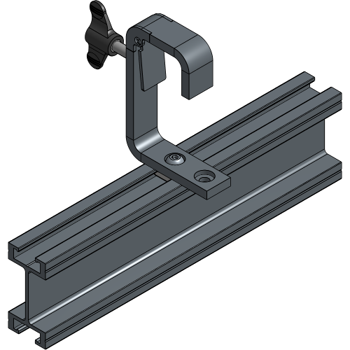
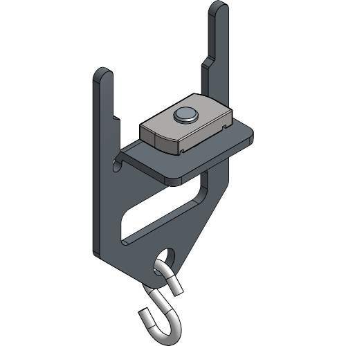
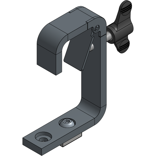
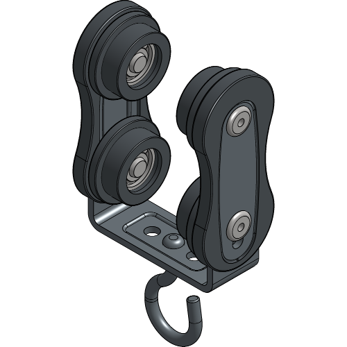
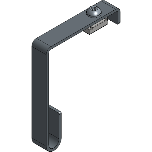
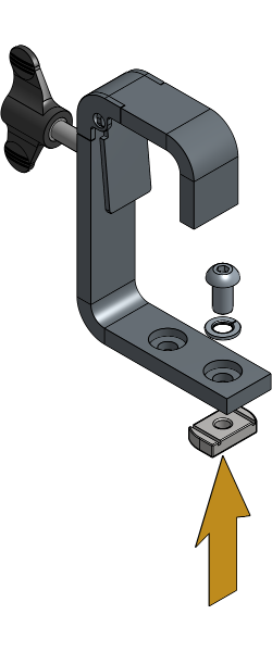
Hook Clamps are a versatile way of suspending your track system that can be used for single track, double track and curved track setups because of the two holes that ar provided. They are designed to accommodate tube diameters of 40 to 50mm, making them suitable for wide range of applications. With their suspension hole for an M10 thread, they provide secure and reliable suspension for your setup.
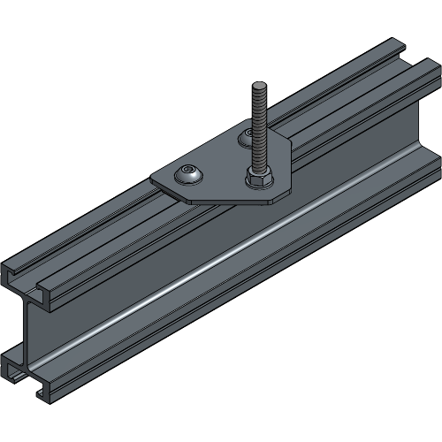
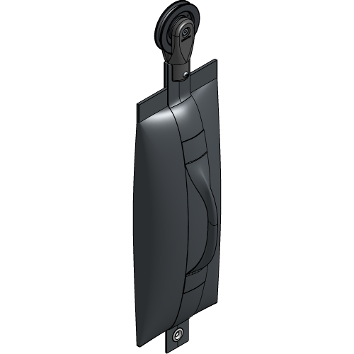
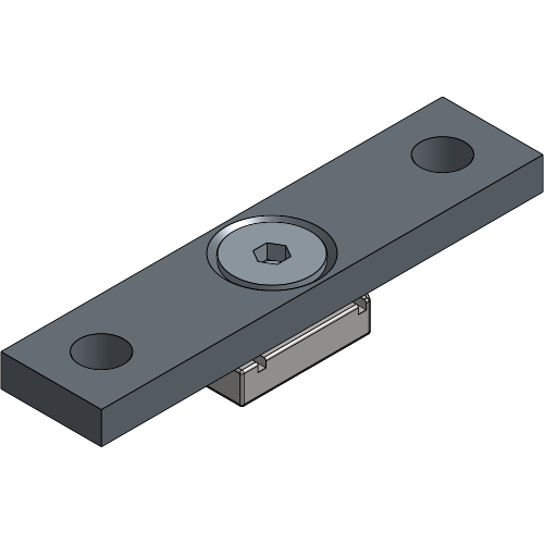
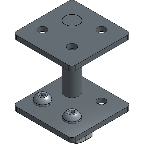
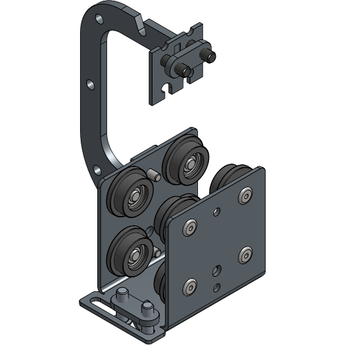
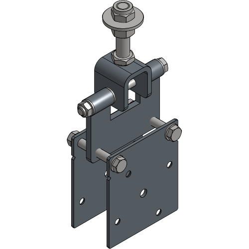
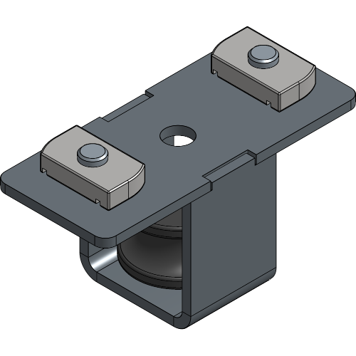
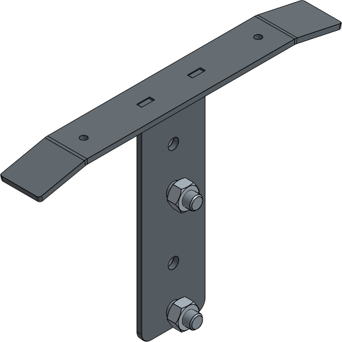
Offset Brackets with a Threaded Rod are a practical suspension choice to suspend a double track and curved track ShowTrack setups. With their hole for an M10 thread, they provide a secure and reliable suspension point for your setup.
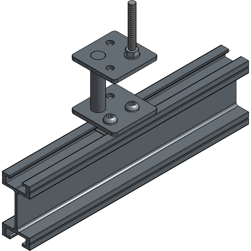
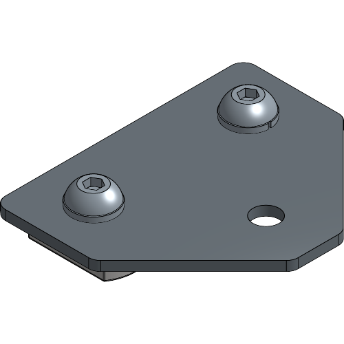
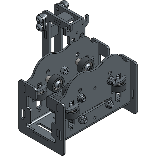
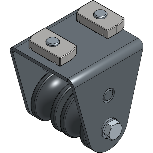
The Offset Bracket is the heavy duty version of the Offset Brackets and is a practical suspension choice to suspend a double track and curved track ShowTrack setup. With their hole for an M10 thread, they provide a secure and reliable suspension point for your setup.
The following ways of determining the number of Runners are mostly standard. There could be exceptions in your system, so counting the grommets in the curtain will always be the best way to be able to know for sure.
Standard, the number of Runners that need to be inserted on a Showtrack system is four Runners per metre of curtain + one extra Runner for every curtain.
Example: 6 m of curtain = (4 x 6) + 1 = 25 Runners

If there is a Carrier included in your ShowTrack system, the number of Runners there need to be inserted is four Runners per metre of curtain.
Example: 6 m of curtain = 4 x 6 = 24 Runners
If there is a Carrier with an overlap included in your ShowTrack system, the number of Runners there need to be inserted is four Runners per metre of curtain - one Runner for every overlap.
Example: 6 m of curtain = (4 x 6) - 1 = 23 Runners
Never exceed the maximum distance approved load capacities.
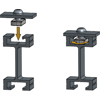
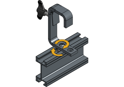
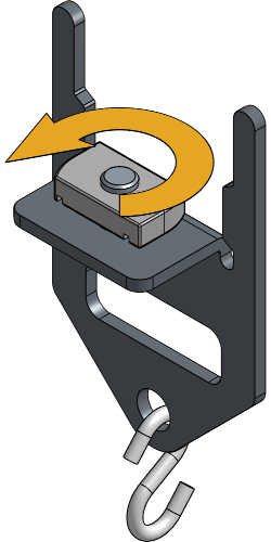
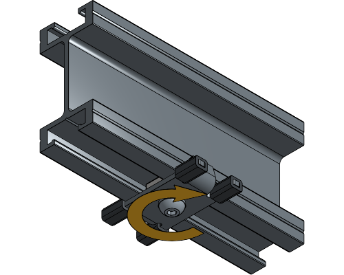
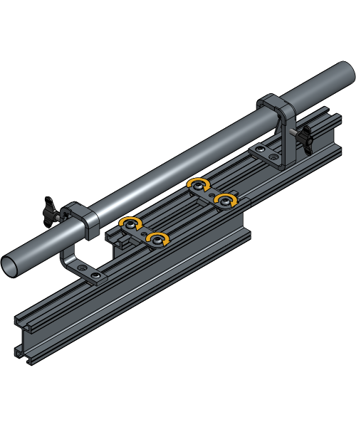
Throughout the manual, components will be inserted into the track with the use of channel nuts. This chapter will show you in detail what should happen each time a channel nut step is mentioned.
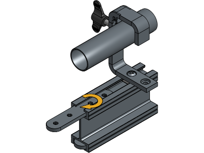
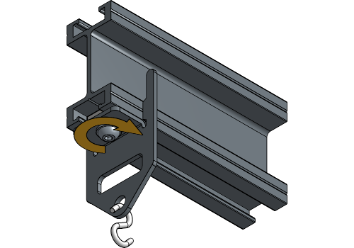
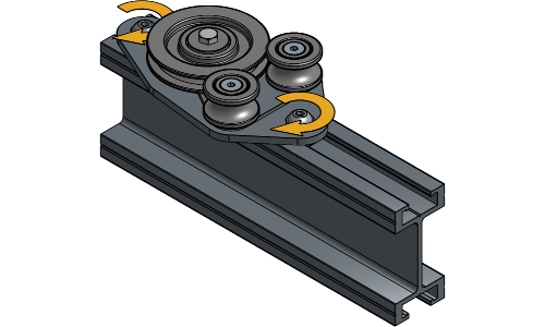
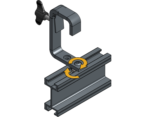
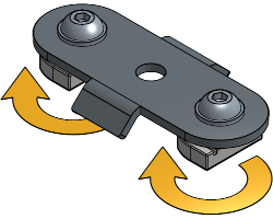
Loosen the channel nut until it fits the track profile, and insert it into the track profile. Rotate the channel nut a quarter turn right.
Keep the channel nut in place and tighten the socket screw. By tightening the socket screw, the channel nut will lock itself on the track.
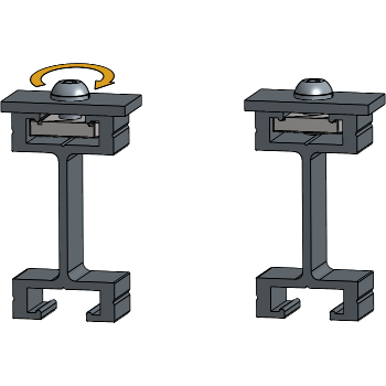
When a channel nut is locked completely, always double check if it’s still positioned correctly to prevent damage or injury.
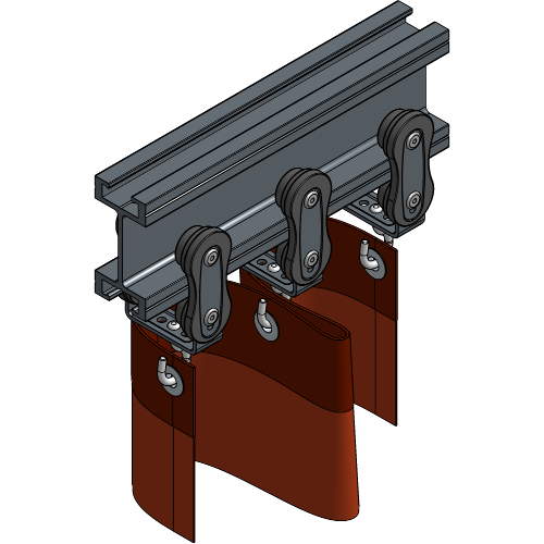
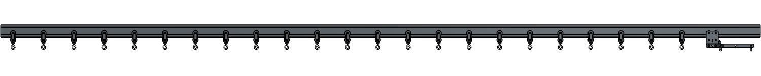
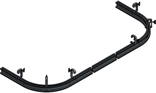
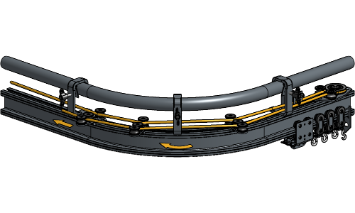
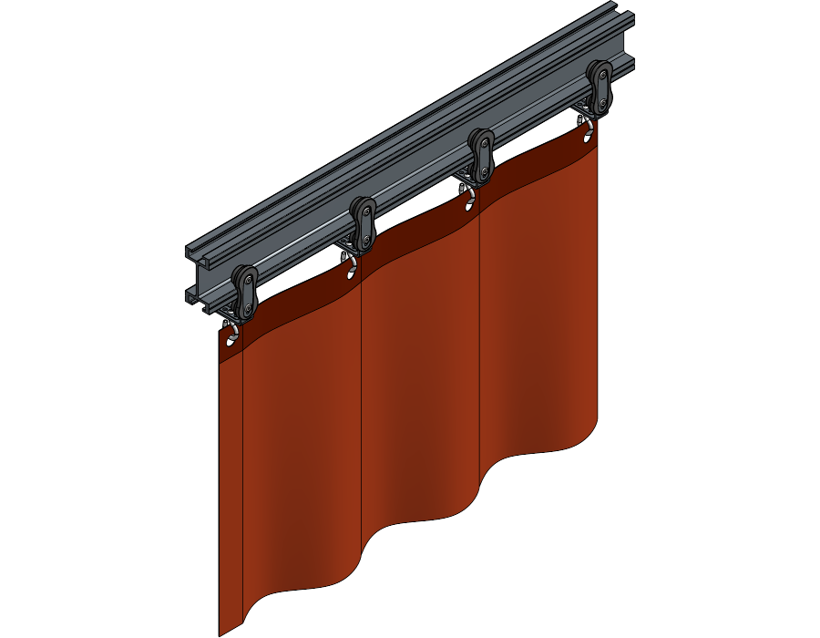
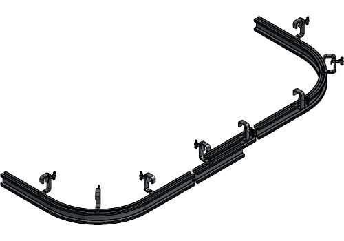
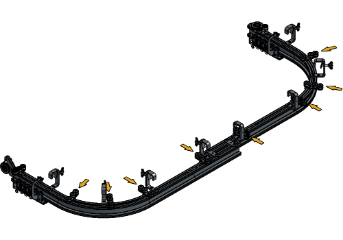
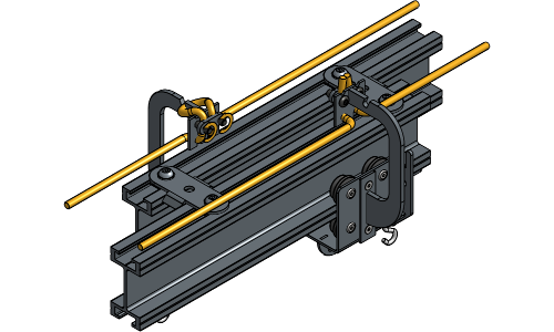
The following steps are used for a Curved Single Track system. If your system is a Curved Double Track, go to the chapter Installation Double Track.
For more information on where to place the suspension components, refer to the Suspension Specifications.
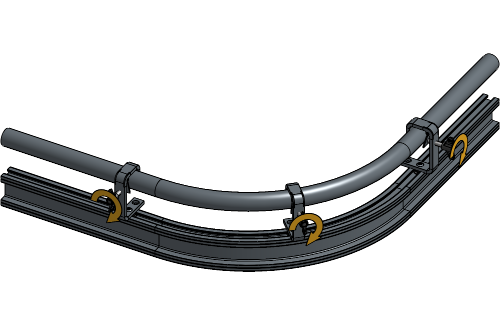
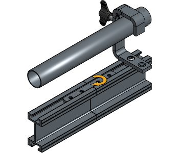
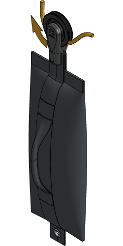
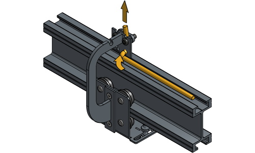
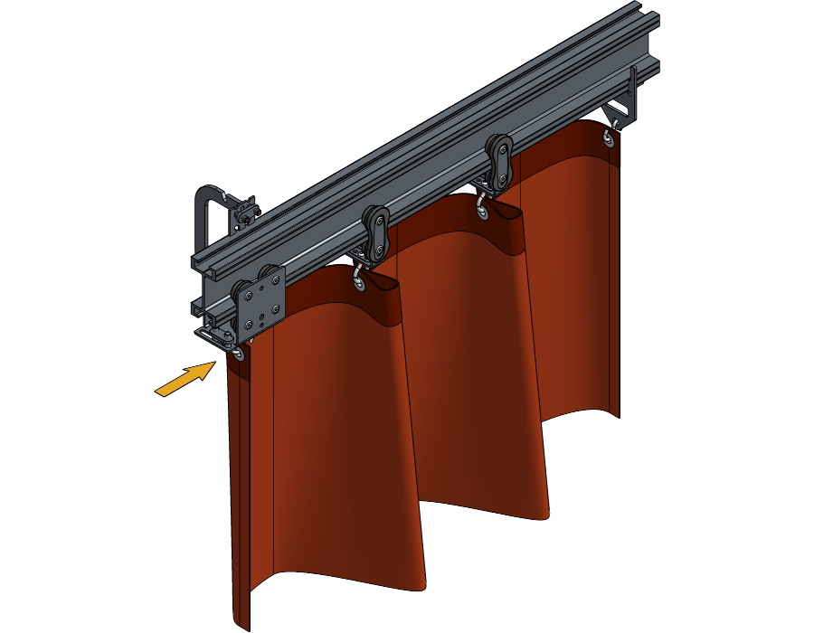
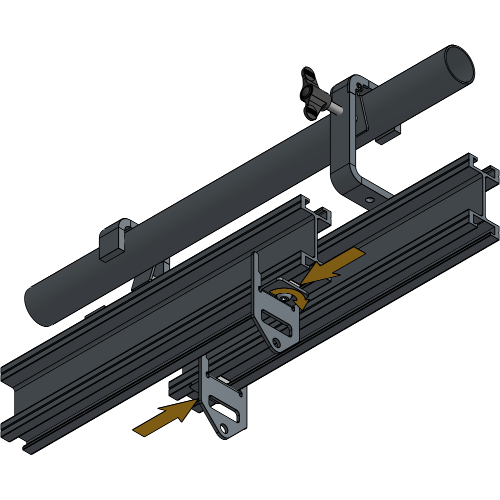
Place the channel nut of the Hook Clamps in the first hole.
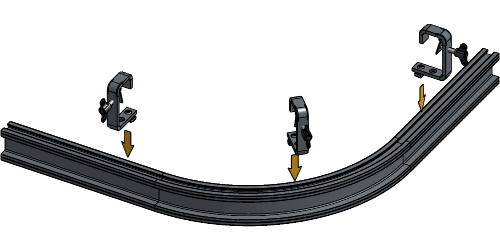
Loosen the channel nut of the Hook Clamps until they fit the track profile, and insert them into the track at the beginning, the middle and at the end of both curves.
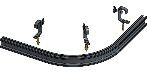
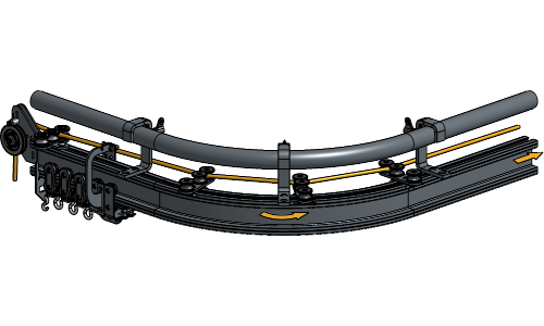
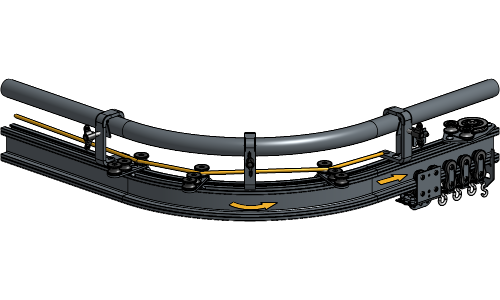
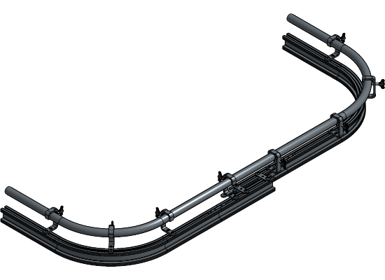
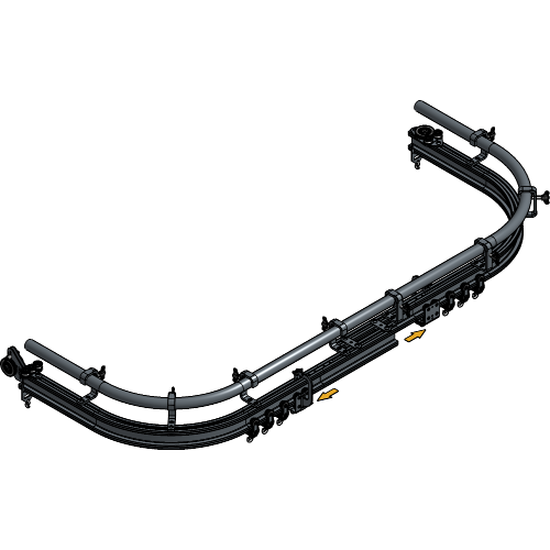
For this setup, it is advised to suspend the two curves first, then build towards the middle and finally the outer ends of the track
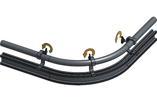
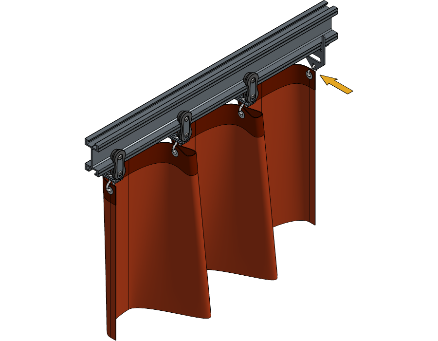
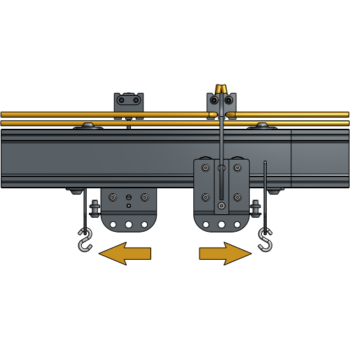
The Hook Clamps of a Curved Track setup need to switch sides at the middle of the track for the Master Carriers to be able to pass.
It is advised to have the opening of the Hook Clamps at the half where you will operate the rope faced towards the front and to have the opening of the Hook Clamps at the other half faced towards the back as shown in the next steps.
Rotate the channel nut a quarter turn right and tighten the socket screw. Repeat these steps for all suspension points.
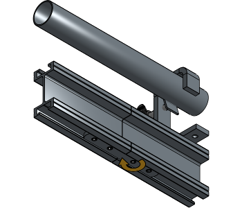
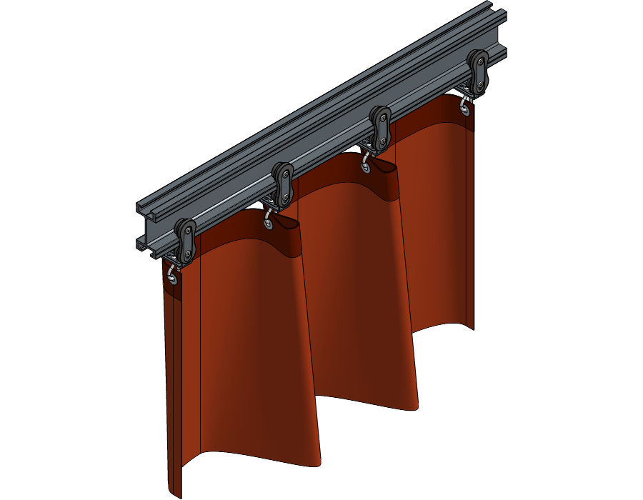
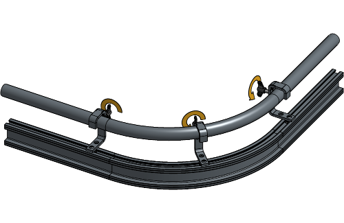
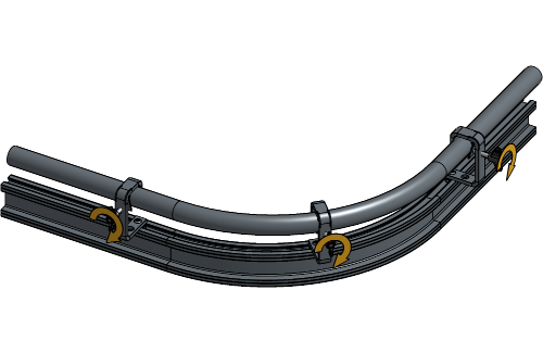
Hang both curves at suspension place of choice and fasten the screw of the Hook Clamps to secure the rail.
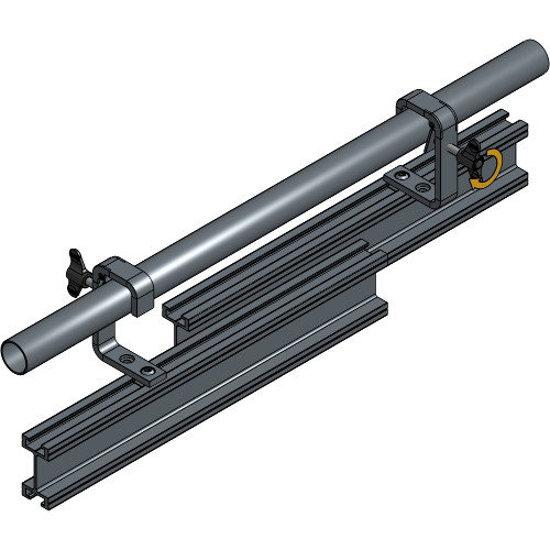
Hang the first piece of straight track next to one of the curves with the Hook Clamps faced in the same direction.
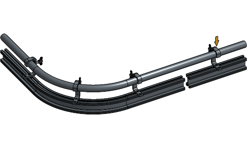
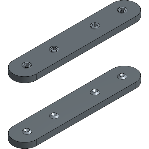
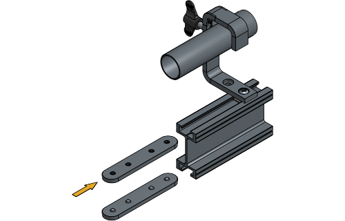
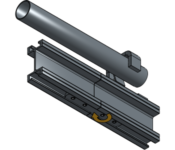
Slide the upper Joint Plate halfway, and the bottom Joint Plate completely into the rail that is already suspended. Fasten one socket screw of each Joint Plate hand tight for stable connecting.
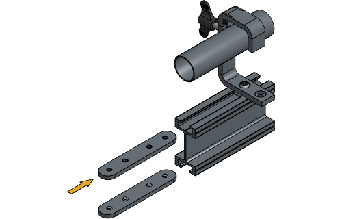
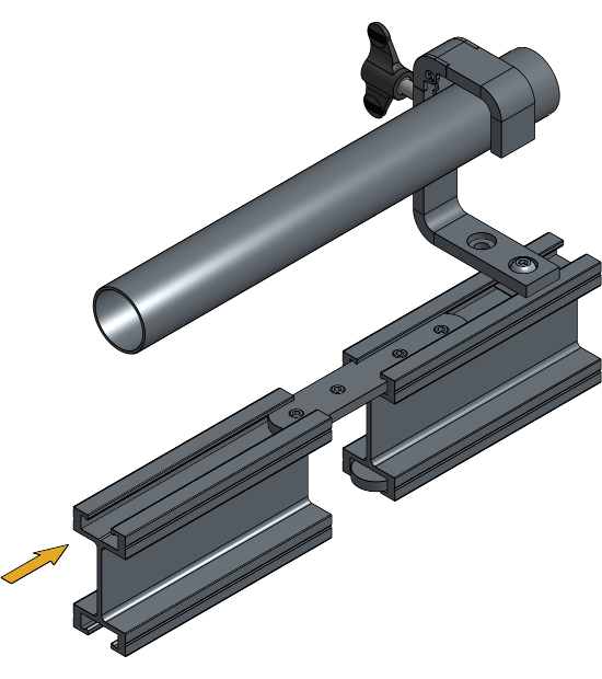
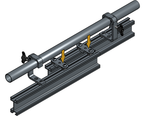
Hang the second part of the track next to the first one and slide it onto the upper Joint Plate.
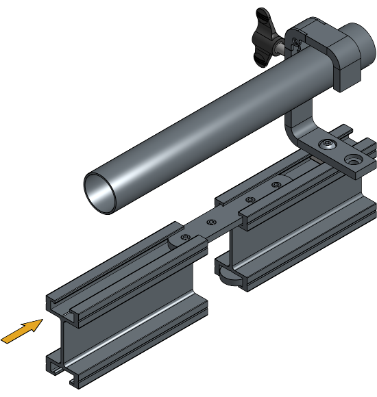
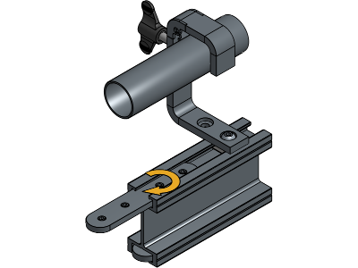
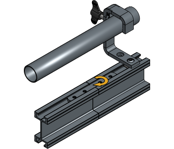
Align both Joint Plates evenly across the track profiles and secure all socket screws.
Repeat these steps until your entire track is suspended and connected.
Make sure that the tracks are aligned correctly. If they are not aligned correctly, some socket screws must be unscrewed or tightened a bit. By not aligning your tracks correctly, there is a possibility that Runners will not roll over the track smoothly and they could get damaged.
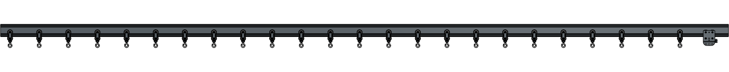
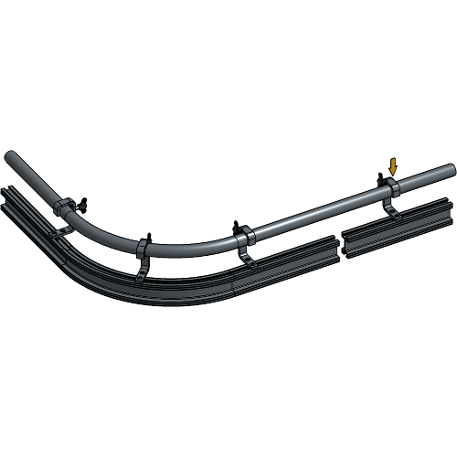
Insert the number of Runners and Master Carriers that are needed for your track system. To know the right number of Runners, refer to the chapter Determining the Number of Runners.
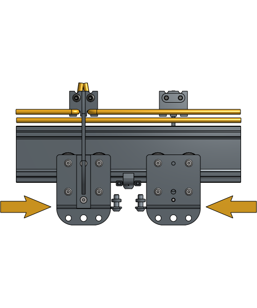
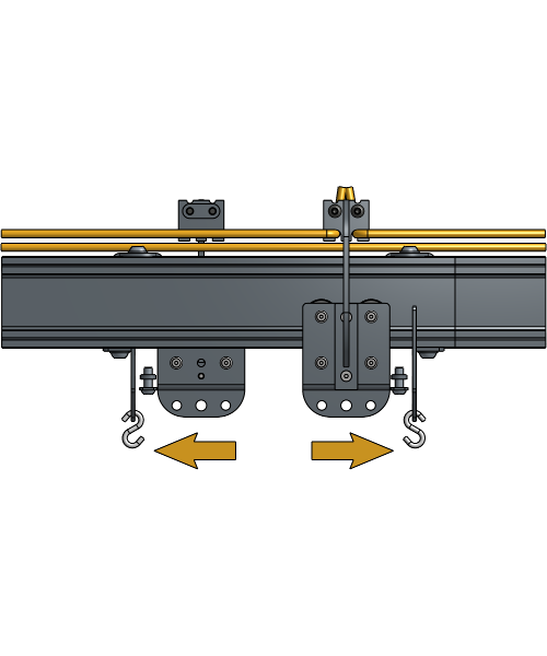
The Master Carriers and Runners need to be inserted at the two ends of the track in the correct way for the Master Carriers to be able to pass.
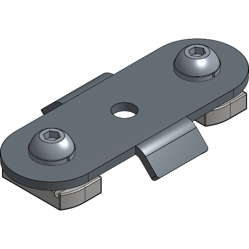
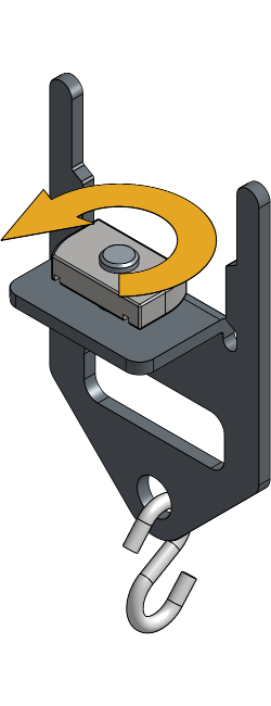
Loosen the channel nut of the End Stops, and turn it until it fits inside the track profile.
If there is an overlap in your curtain, there need to be Overlap Arm sets installed on the Master Carriers. To know how to install the Overlap Arm sets on the Master Carriers, refer to the chapter Placing the Overlap Arms.
Insert both End Stops into the track profile at the end of the track with the plate directed towards the middle. Rotate the Channel Nuts a quarter turn right and tighten the socket screws.
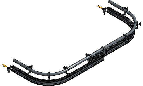
If a RopeAssist is being used, place the End Stop at the side where the rope will be operated about 13 cm from the end of the track.
If a Motor is being used, place the End Stop at the side where the rope will be operated about 23 cm from the end of the track.
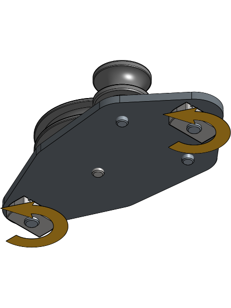
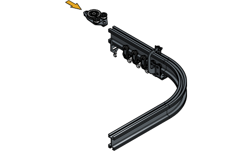
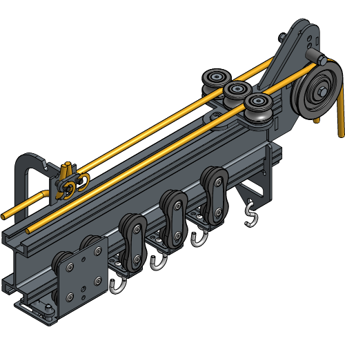
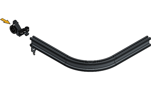
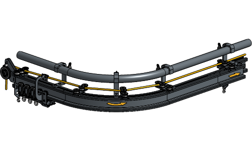
Loosen the channel nut of the Head Pulley until it fits inside the track profile.
Insert the Head Pulley at the end of the track on the side where the rope needs to be operated. Rotate the channel nut a quarter turn right and tighten the socket screw.
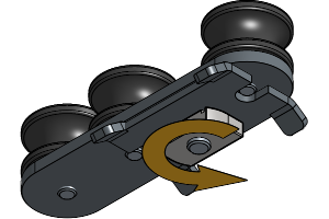
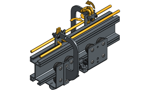
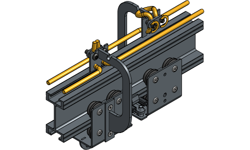
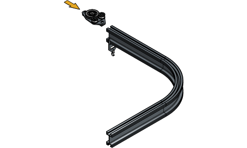
Loosen the channel nuts of the Return Pulley until they fit inside the track profile.
Insert the Return Pulley at the end of the track next to the End Stop. Rotate the channel nuts a quarter turn right and tighten the socket screws.
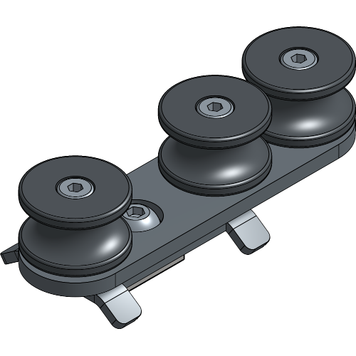
Loosen the Channel nut of the Curve Rope Guides until it fits inside the track profile and insert one every 3 m at each side of the track. Make sure they are oriented for the Master Carriers to be able to pass.
In the curves, there should be a Curve Rope Guide at the beginning and end of the curve and every 30 cm in between.
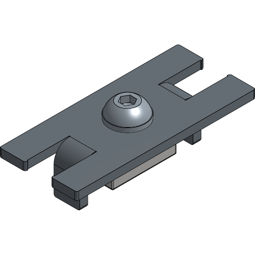
If you have a central opening in your ShowTrack system, insert a Flat End Stop at the place of overlap with the correct amount of Runners at each side.
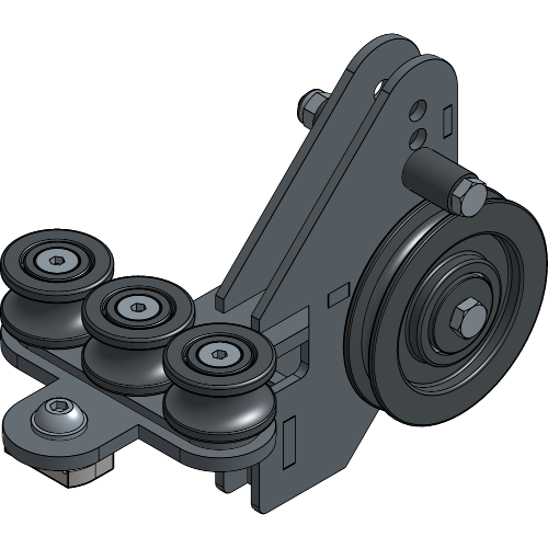
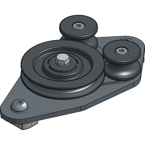
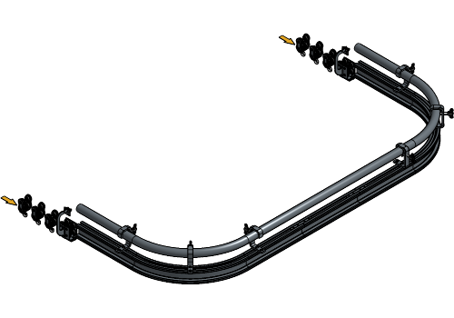
Define the rope operation system your ShowTrack contains and follow the associated steps
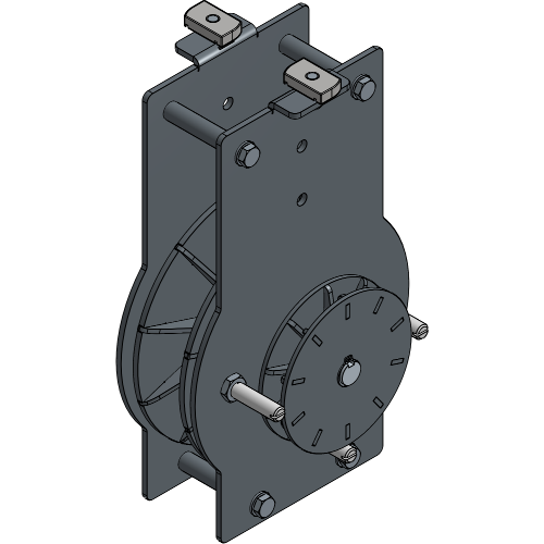
Guide the rope through the Weighted Return Pulley.
Guide the rope through the backside of the Head Pulley.
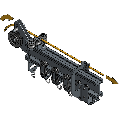
Guide the rope through all Curve Rope Guides towards the Return Pulley.
Guide the rope through the Return Pulley.
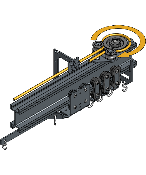
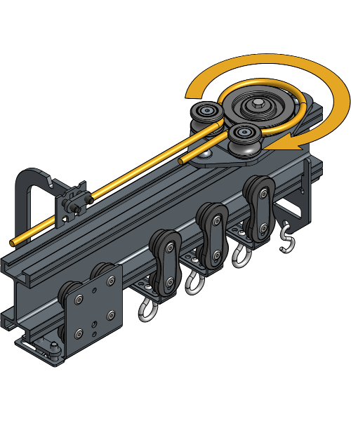
Guide the rope back through all Curve Rope Guides. End at the Carrier of which the Rope Clamp is located at this side of the track.
Clamp the first rope end in the Rope Clamp of that Carrier.

Guide the second rope end through the front side of the Head Pulley and all Curve Rope Guides and stop at the same Carrier where the first rope end is clamped.
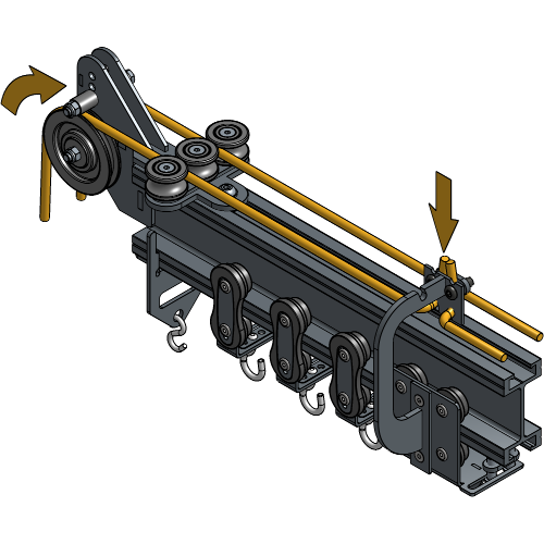
Make sure the rope is tight and the Weighted Return Pulley is about 50 cm off the ground.
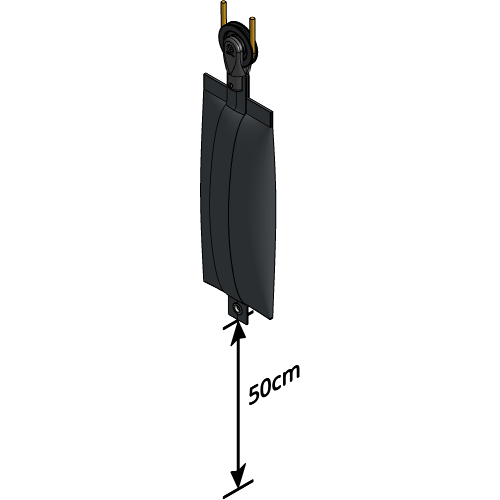
Clamp the second rope end in the same rope clamp where the first rope end is clamped.
If you have a central opening, align both Carriers at the Flat End Stop.

Clamp the rope in the rope clamp of the remaining Carrier and tighten the screws.
All steps from the Weighted Return Pulley are completed
For further installation steps, go to to Placing the Overlap Arms
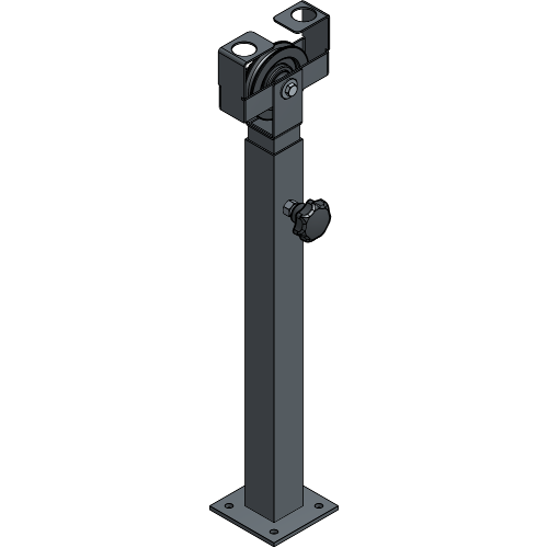
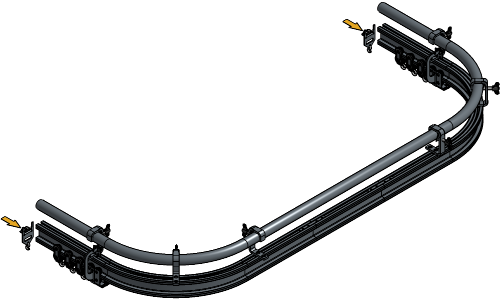
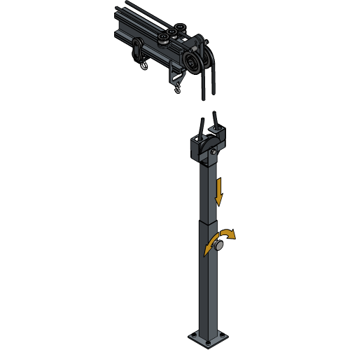
Secure the Floor Fixed Return Pulley into the floor, in line with the Head Pulley.
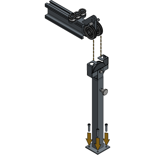
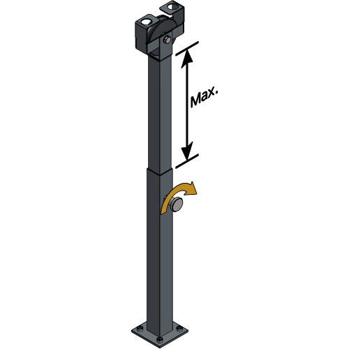
Extend the Floor Fixed Return Pulley to the maximum length by unfastening and fastening the knob at the side.
Guide the rope through the Floor Fixed Return Pulley from front to back.
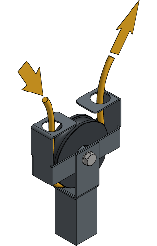
Guide the rope through the backside of the Head Pulley.
Guide the rope through all Curve Rope Guides towards the Return Pulley.

Guide the rope through the Return Pulley.
Guide the rope back through all Curve Rope Guides. End at the Carrier of which the Rope Clamp is located at this side of the track.


Clamp the first rope end in the Rope Clamp of that Carrier.
Guide the second rope end through the front side of the Head Pulley and all Curve Rope Guides and stop at the same Carrier where the first rope end is clamped.
Make sure the rope is tight and clamp the second rope end in the same rope clamp where the first rope end is clamped.
If you have a central opening, align both Carriers at the Flat End Stop.
Clamp the rope in the rope clamp of the remaining Carrier and tighten the screws.
Adjust the height of the Floor Fixed Return Pulley to change the rope tension.
All steps from the Floor Fixed Return Pulley are completed
For further installation steps, go to to Placing the Overlap Arms
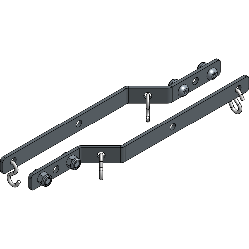
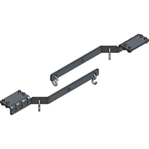
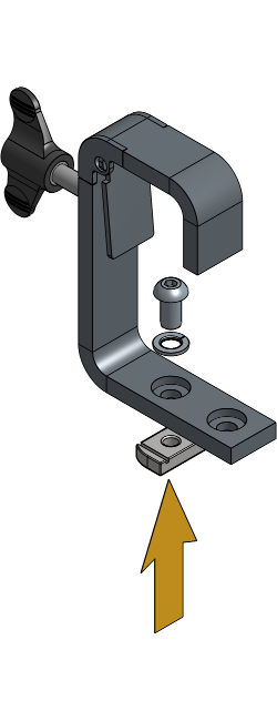
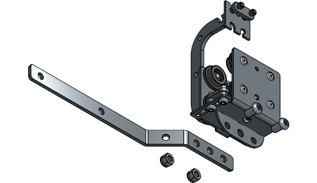
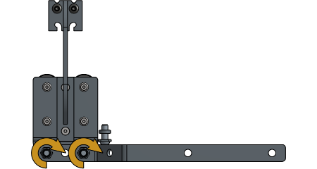
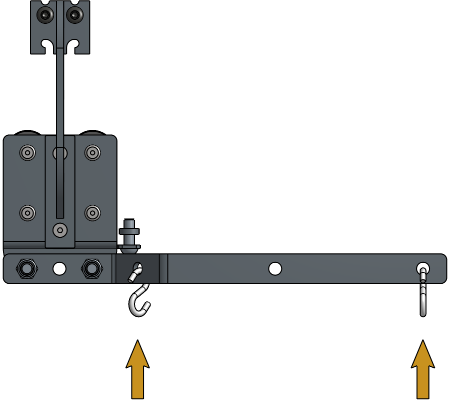
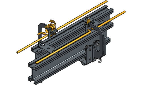
Lay the Overlap Arms in the correct “left before right” position.
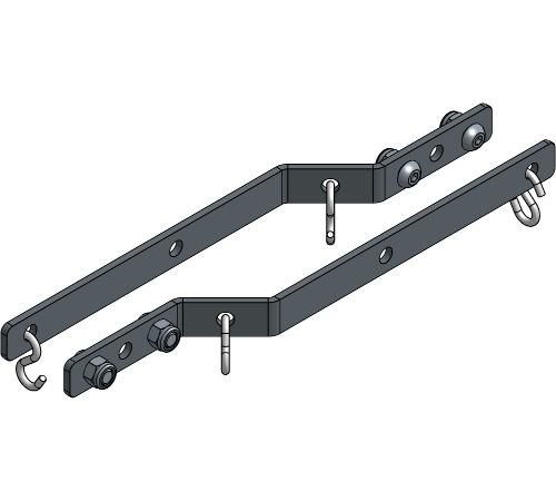
Secure the Overlap Arm to the Carrier with bolts in the first and third hole of the Overlap Arm.
Place an S-Hook in the first and last hole of the Overlap Arm that are available.
If Master Carriers are used, attach the start of the curtain to the S-hooks of the Master Carriers and work towards the end of the track.
If one side of the curtain needs to be kept in place at all times, place an S-hook on the desired End Stop and attach one grommet to the S-hook.
It is important to fully open your curtain and then attach it to the End Stop to avoid ripping your curtain if it is not the correct size.
Take two grommets together and attach them to the same S-Hook.
Attach each grommet to a separate S-Hook.
Your Curved Rope Operated Single Track ShowTrack is now completely installed and ready to use!
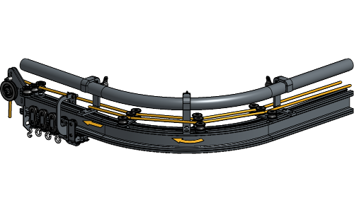
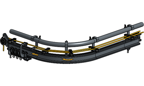
The following steps are used for a Curved Double Track system. If your system is a Curved Single Track, go to the chapter Installation Single Track.
For more information on where to place the suspension components, refer to the Suspension Specifications.
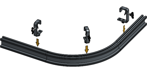
Place the channel nut of the Hook Clamp in the second hole.
Loosen the channel nut of the hook clamps until they fit the track profile, and insert them into the track at the beginning, the middle and at the end of both curves.

For this setup, it is advised to suspend the two curves first, then build towards the middle and finally the outer ends of the track.
It is advised to have the opening of the Hook Clamps at the half where you will operate the rope faced towards the front and to have the opening of the Hook Clamps at the other half faced towards the back as shown in the next steps.
Rotate the channel nut a quarter turn right and tighten the socket screw. Repeat these steps for all suspension points.
Hang both curves at suspension place of choice and fasten the screw of the Hook Clamps to secure the rail.
If you wish to follow the standard placement for theatres, make sure the left part of the track is placed in front.
Hang the first piece of straight track next to one of the curves with the Hook Clamps faced in the same direction.
Slide the upper Joint Plate halfway, and the bottom Joint Plate completely into the rail that is already suspended. Fasten one socket screw of each Joint Plate hand tight for stable connecting.
Hang the second part of the track next to the first one and slide it onto the upper Joint Plate.
Align both Joint Plates evenly across the track profiles and secure all socket screws.
When arriving at the place of overlap at the end, hang that part of the track on the other side and fasten the screw of the Hook Clamps hand-tight for easier installation of the Overlap Clips.
Loosen the channel nuts of the Overlap Clips until they fit the track profile and insert them at the overlapping parts of the Track.
Rotate the channel nut a quarter turn right and tighten the socket screws to secure the Overlap Clips.
Repeat these steps until your entire track is suspended and connected.
Make sure that the tracks are aligned correctly. If they are not aligned correctly, some socket screws must be unscrewed or tightened a bit. By not aligning your tracks correctly, there is a possibility that Runners will not roll over the track smoothly and they could get damaged.
Loosen the channel nut of the End Stops, and turn it until it fits inside the track profile.
Insert one End Stop into the track profile at the outer end of both tracks with the plate directed towards the middle and tighten the socket screw.
If you are using a RopeAssist, place the End Stop at the side where the rope will be operated about 13 cm from the end of the track.
If you are using a Motor, place the End Stop at the side where the rope will be operated about 23 cm from the end of the track.
Loosen the channel nut of the Head Pulley until it fits inside the track profile.
Insert the Head Pulley at the end of the track on the side where the rope needs to be operated. Rotate the channel nut a quarter turn right and tighten the socket screw.
Loosen the channel nuts of the Return Pulley until they fit inside the track profile.
Insert the Return Pulley at the other end of the track. Rotate the channel nuts a quarter turn right and tighten the socket screws.
Insert the number of Runners and Master Carriers that are needed for your track system. To know the right number of Runners, refer to the chapter Determining the number of Runners.
Insert two End Stops the same way at the overlap of the track.
Loosen the Channel nut of the Curve Rope Guides until it fits inside the track profile and insert one every 3 m at each side of the track. Make sure they are oriented for the Master Carriers to be able to pass.
In the curves, there should be a Curve Rope Guide at the beginning and end of the curve and every 30 cm in between.
Define the rope operation system your ShowTrack contains and follow the associated steps
Guide the rope through the Weighted Return Pulley.
Guide the rope through the backside of the Head Pulley.
Guide the rope through all Curve Rope Guides towards the Return Pulley.
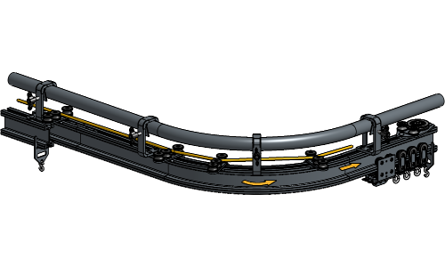
Guide the rope through the Return Pulley.
Guide the rope back through all Curve Rope Guides. End at the Carrier closest to the Head Pulley.
Clamp the first rope end in the Rope Clamp of that Carrier.
Guide the second rope end through the front side of the Head Pulley and all Curve Rope Guides and stop at the same Carrier.
Make sure the rope is tight and the Weighted Return Pulley is about 50 cm off the ground.
Clamp the second rope end in the same rope clamp where the first rope end is clamped.
Align both Carriers at the place of overlap.
Clamp the rope in the rope clamp of the remaining Carrier and tighten the screws.
All steps from the Weighted Return Pulley are completed
For further installation steps, go to to Installing the Curtain
Secure the Floor Fixed Return Pulley into the floor, in line with the Head Pulley.
Extend the Floor Fixed Return Pulley to the maximum length by unfastening and fastening the knob at the side.
Guide the rope through the Floor Fixed Return Pulley from front to back.
Guide the rope through the backside of the Head Pulley.
Guide the rope through all Curve Rope Guides towards the Return Pulley.

Guide the rope through the Return Pulley.
Guide the rope back through all Curve Rope Guides. End at the Carrier closest to the Head Pulley.
Clamp the first rope end in the Rope Clamp of that Carrier.
Guide the second rope end through the front side of the Head Pulley and all Curve Rope Guides and stop at the same Carrier.
Make sure the rope is tight and clamp the second rope end in the same rope clamp where the first rope end is clamped.
Align both Carriers at the place of overlap.
Clamp the rope in the rope clamp of the remaining Carrier and tighten the screws.
Adjust the height of the Floor Fixed Return Pulley to change the rope tension.
All steps from the Floor Fixed Return Pulley are completed
For further installation steps, go to to Installing the Curtain
If Master Carriers are used, attach the start of the curtain to the S-hooks of the Master Carriers.
If one side of the curtain needs to be kept in place at all times, place an S-hook on the desired End Stop and attach one grommet to the S-hook.
It is important to fully open your curtain and then attach it to the End Stop to avoid ripping your curtain if it is not the correct size.
Take two grommets together and attach them to the same S-Hook.
Attach each grommet to a separate S-Hook.
Your Curved Rope Operated Double Track ShowTrack is now completely installed and ready to use!
Periodic, regularly scheduled maintenance inspections are necessary for any mechanical system. A theatrical curtain track system is no different. It has components that must be inspected, adjusted, maintained and replaced. To ensure the safety and proper functioning of the system, it is essential to establish a routine inspection.
Please follow the provided schedule below as the minimum maintenance program. After the operating personnel gains experience with the system within the initial year, additional measures and adjustments may be implemented based on your systems specific needs.
| Every week | Every month | Every six months | |
|---|---|---|---|
| Operate the curtain and check if it operates smoothly. | X | ||
| Listen for unusual noise coming from Runners and Carriers. | X | ||
| Listen for unusual noise coming from all Pulleys. | X | ||
| Inspect the conditions of the rope. | X | ||
| Inspect the tension of the rope. | X | ||
| Inspect the Runners, Carriers, Pulleys and Rope Clamps for abnormalities. | X | ||
| Inspect if the curtain is attached to the Runners and Carriers correctly. | X | ||
| Inspect if the tracks are aligned properly. | X | ||
| Inspect the track channel for debris and dust. | X | ||
| Inspect if the track is attached to the building structure correctly. | X |
To effectively maintain your theatrical curtain track system, it is recommended to regularly use it as it helps distribute the grease evenly. Instances of above-average use or operating the curtain in surroundings with high humidity, dust or extreme temperature changes may require shorter intervals than indicated in the Care & Maintenance.
As with any system, it is possible for issues to arise in a theatrical curtain track system. If the curtain stops operating smoothly, we recommend following these troubleshooting steps as an initial check to address the problem.
Check if any objects are obstructing the track.
Check for damage to the track, repair or replace if damage is found.
Check for debris in the track channel and Runners, remove carefully if debris is found.
Check for damaged Runners, replace if necessary.
Check if all tracks are aligned properly without gaps, if not, adjust the Joint set to align them.
Check if the Joint set screws aren’t tightened too much, over-tightened Joint sets could result in bent tracks.
Check if the rope has lost any tension and, if necessary, add more tension by adjusting the rope.
Check the connection between the rope ends and the Rope Clamps on the Master Carriers. Reattach properly if necessary.
When the curtain slides out of the track, check if the End Stops are secure and present. Tighten or replace them if necessary.
For more technical assistance, please contact your local ShowTex
office.
The address and contact information can be found on our website:
www.showtex.com