ShowTrack
Rope Drive Installation
Annex
Annex
No part of this publication may be duplicated or edited in any form or by any means, including any type of electronic or mechanical method without prior written permission from ShowTex.
ShowTex and its employees are fully aware of their task to provide a reliable edition of this document. Nevertheless, they cannot accept any form of liability for the direct or indirect consequences of imperfections that might remain in this edition. The material in this manual is subject to change without notice.
ShowTex warrants that its mechanical and technical products, when delivered in new condition, in original packing, sold directly and used in normal conditions are free from any defects in manufacturing, materials and workmanship. For more information about your local warranty terms, please check our website or contact your local ShowTex office.
All products from the ShowTex Rental range are supposed to be returned in the same state as they were rented. Please treat our products with care, allowing the next user to enjoy the products as much as you did. The rented products are internally checked according to the general rental conditions. Be sure to check our rental guidelines on our website before installing and using this product: ShowTex rental guidelines
Read and understand this user manual before installing and or operating the system. Failure to follow the instructions in this document could result in serious injury!
Following the guidelines of this manual will reduce the risk of damaging the equipment or injuring yourself and the people around you. Nevertheless, ShowTex cannot be held accountable for any use or misuse of the equipment and supplies.
Damage to the system caused by any other method of installation than the one shown in this manual can only be repaired or fixed at the customer’s expense.
As a result of the above warning, any ShowTex product must be installed and operated by a qualified technician who knows its capabilities as well as its limitations.
In case you are uncertain about the eligibility of any hardware in your product, please get in touch with your local ShowTex office to receive additional guidance.
Thank you for choosing for ShowTex and purchasing one of our products. We want to ensure that your experience is as smooth and safe as possible, so we kindly request that you take a few moments to carefully read this manual before installing your new system.
This manual contains important information that will help you comply with health and safety regulations, as well as provide guidance on how to safely install, operate and maintain your product. Our team has taken great care to ensure that this manual is easy to understand and follow, using straightforward language and clear illustrations.
If you have any questions or concerns regarding the installation or use of your product, please feel free to contact your local ShowTex office. Our knowledgeable team members are always available to assist you and answer any questions you may have.
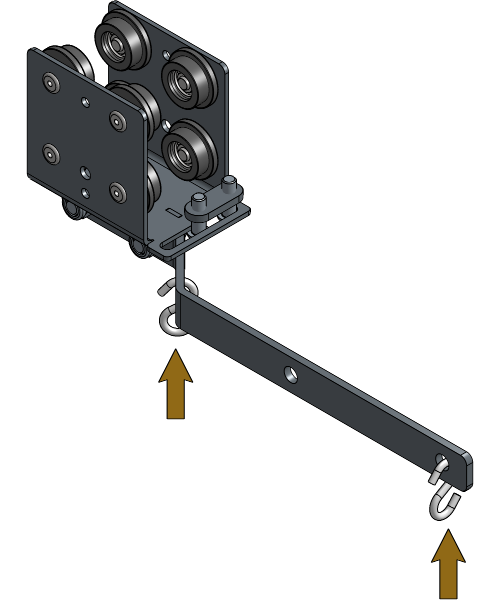
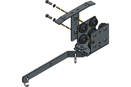
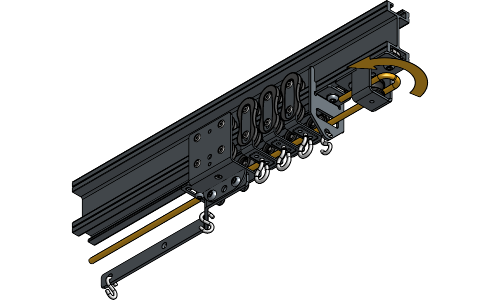
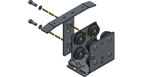
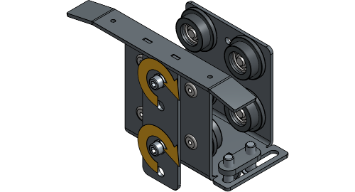
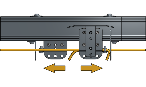
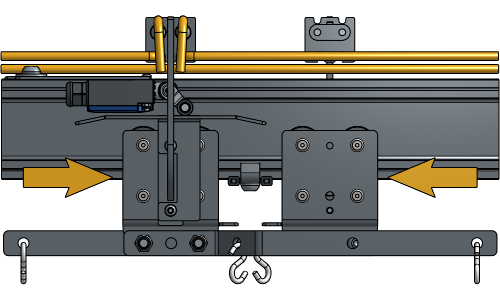
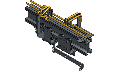
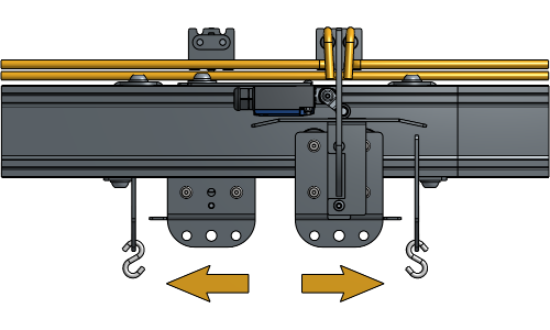
Lay the Overlap Arms in the correct “left before right” position.
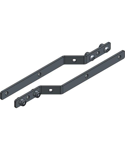
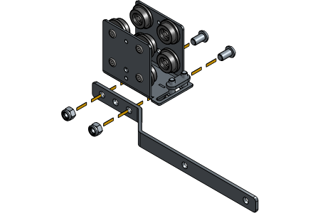
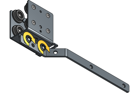
Secure the Overlap Arm to the Carrier with bolts in the first and third hole of the Overlap Arm.
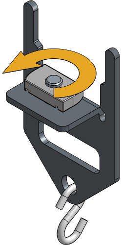
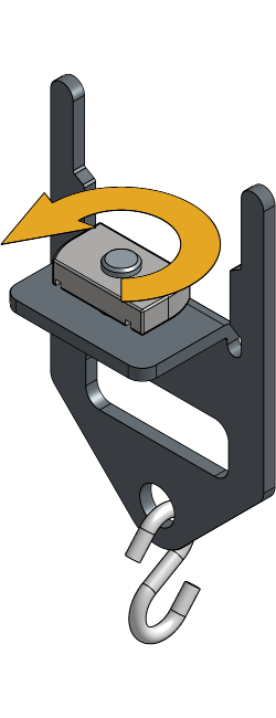
Place an S-Hook in the first and last hole of the Overlap Arm that are available of both Master Carriers.
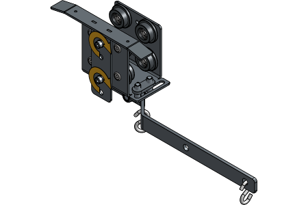
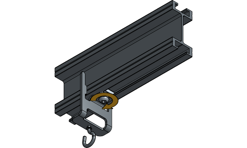
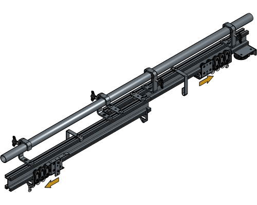
Secure the Limit Switch Ski on the Carrier that will be closest to the motor on the same side as the Overlap Arm. The spacers should face the body of the Carrier.
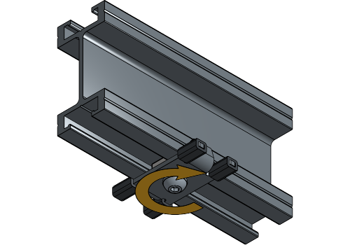
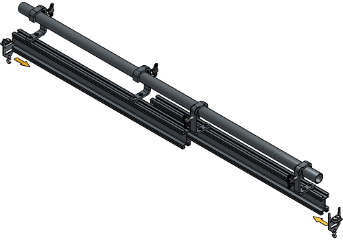
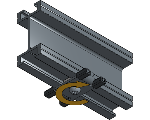
Loosen the channel nut of the End Stops, and turn it until it fits inside the track profile.
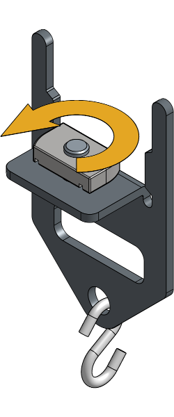
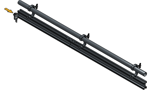
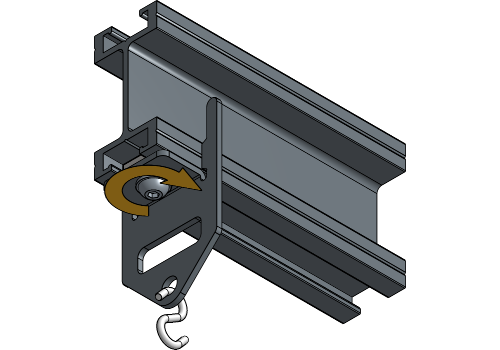
Insert one End Stop into the track profile at the place where you will operate the rope with the plate directed towards the middle at about 15 cm from the end of the track. Rotate the channel nut a quarter turn right and tighten the socket screw.
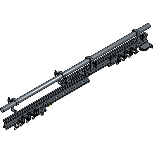
Insert the number of Runners and Master Carriers that are needed for your track system. To know the right number of Runners, refer to the chapter Determining the Number of Runners.
Insert the other End Stop the same way at the other end of the track at 15 cm from the end of the track.
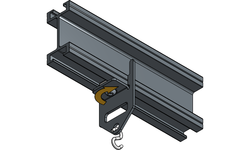
Loosen the channel nuts of the Return Pulley until they fit inside the track profile.
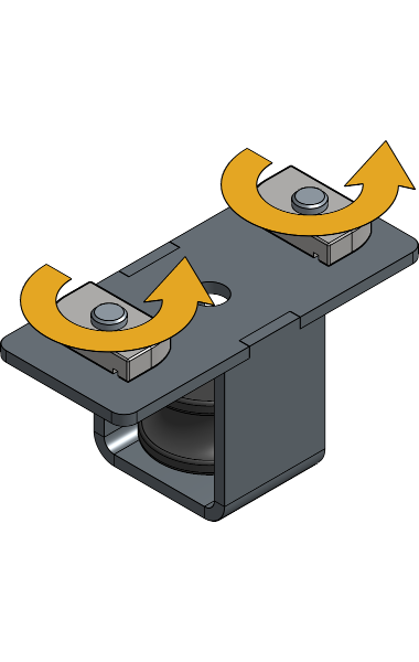
Insert the Return Pulley at the end of the track next to the End Stop. Rotate the channel nuts a quarter turn right and tighten the socket screws.

If you have a central opening in your ShowTrack system, insert a Flat End Stop at the place of overlap with the correct amount of Runners at each side.
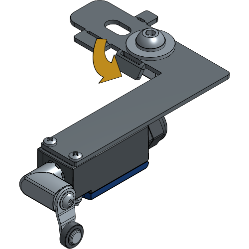
The following steps are for a setup with a standard 50 kg Master Carrier. When using the 100 kg or 350 kg Master Carrier, the Limit Switch is mounted on top of the plate with the wheel facing down.
When using Scenery or Quick Release Carriers of 100 or 350 kg, the first Limit Switch is placed at 10 cm distance from the first Runner and the second Limit Switch is placed at 12 cm distance from the Flat End Stop.
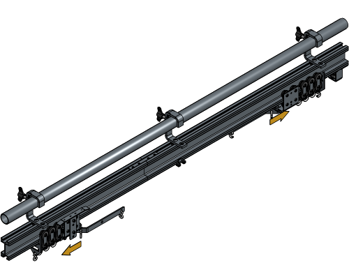
Slide all Runners and Carriers towards the outer End Stops in an open curtain position.
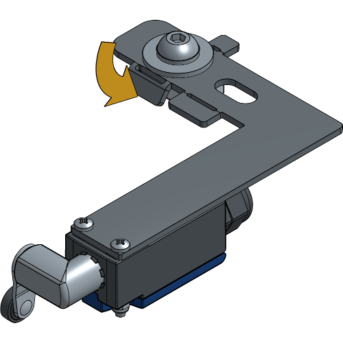
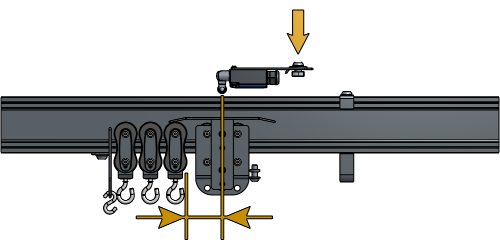
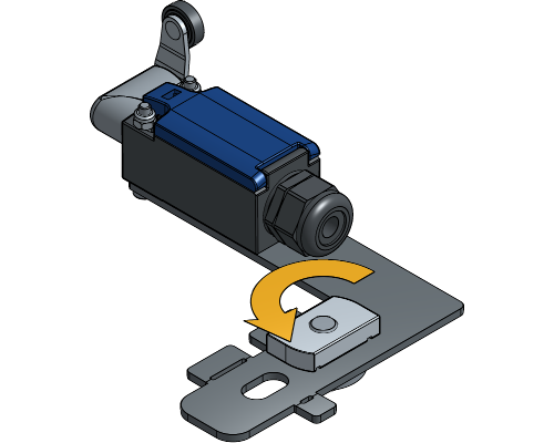
Loosen the channel nuts of the Limit Switches.
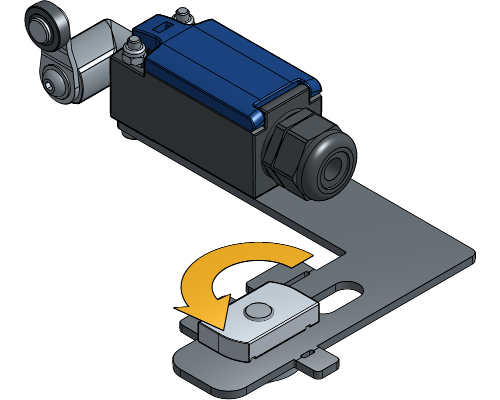
Bend the outer lip from both Limit Switch Plates about 30° towards the channel nut. This will stabilize the Limit Switch when mounted.
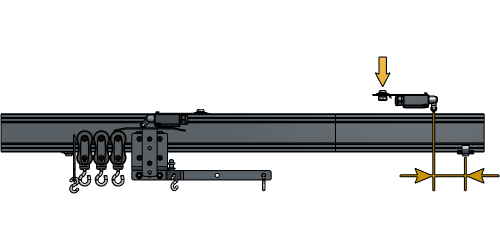
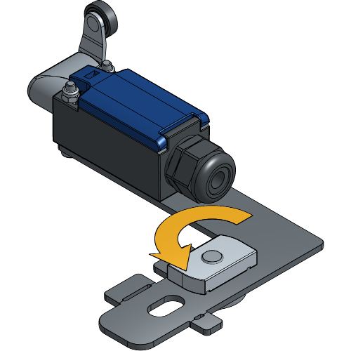
Place the first Limit Switch with the wheel at 7 cm distance from the first Runner and tighten the channel nut.
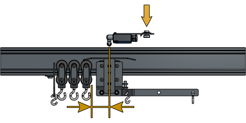
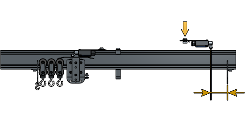
Place the second Limit Switch with the wheel at 9 cm from the Flat End Stop and tighten the channel nut.
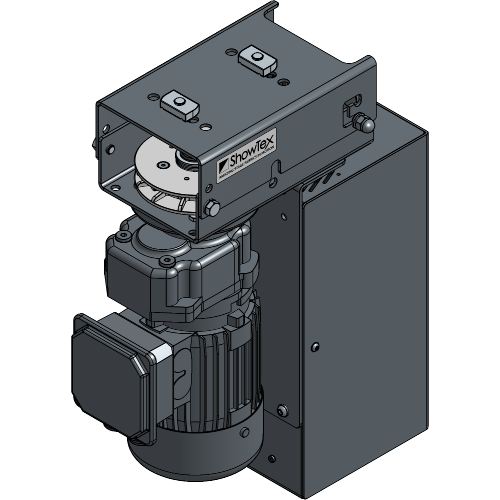
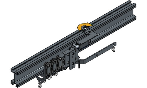
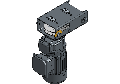
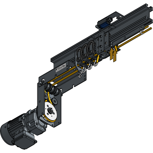
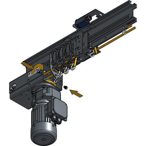
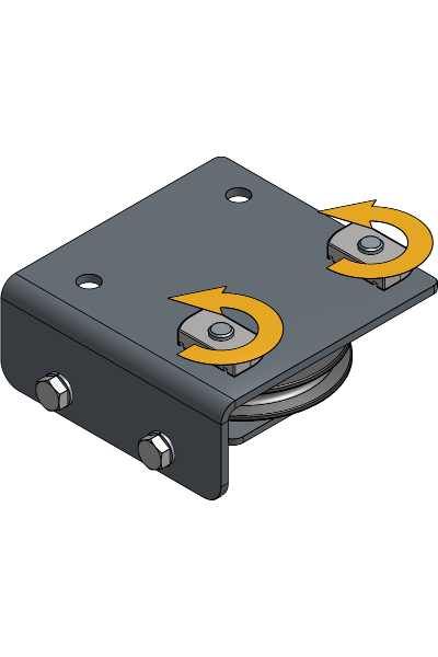
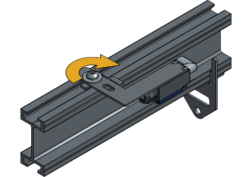
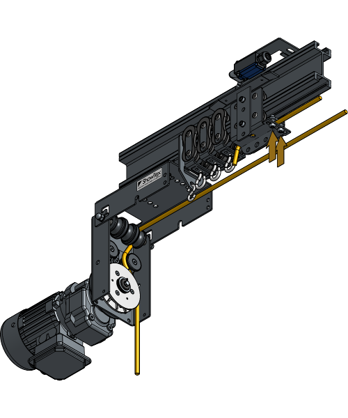
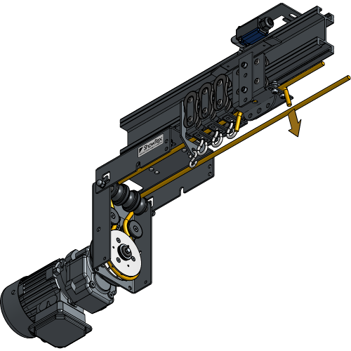
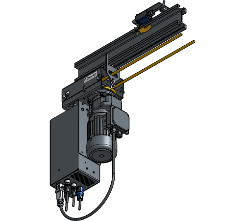
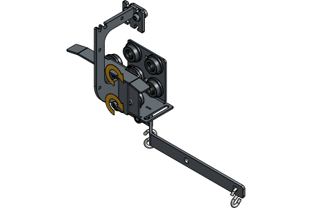
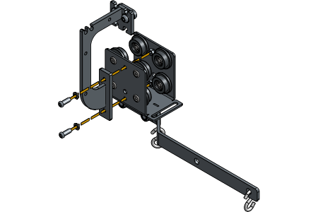
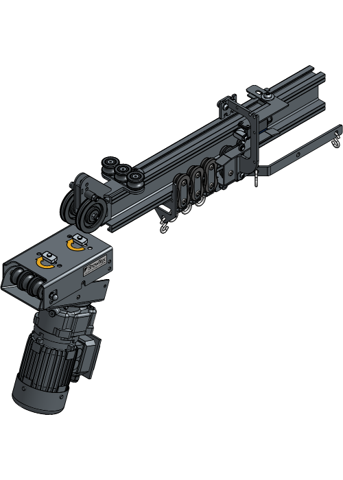
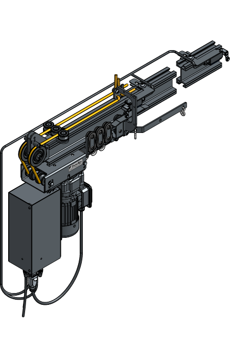
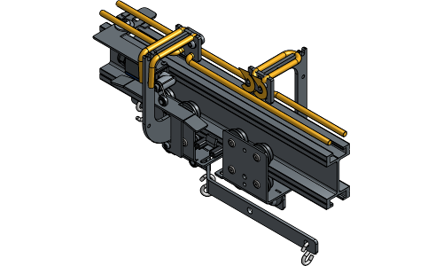
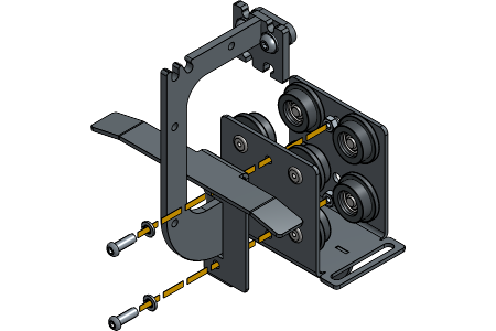
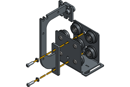
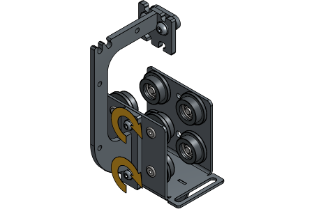
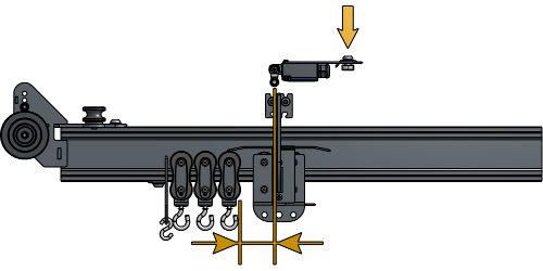
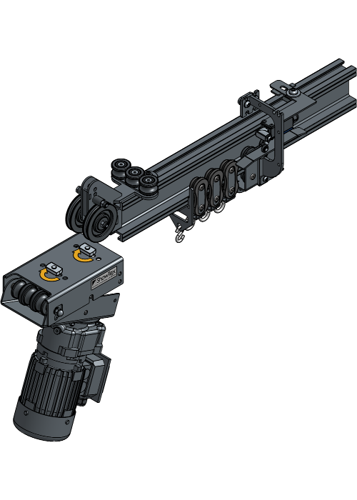
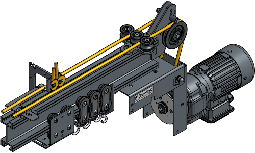
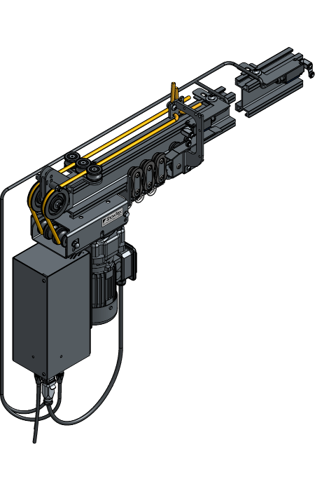
Loosen and remove the bolts of the Rope Transmission.
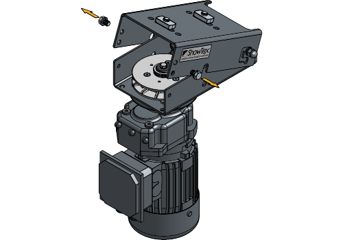
Remove the channel nuts and place them in the second hole of the Rope Transmission.
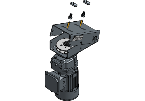
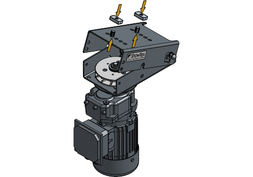
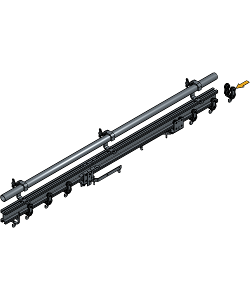
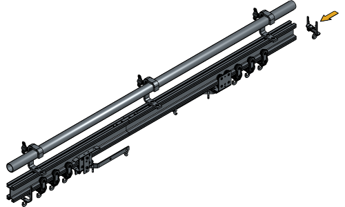
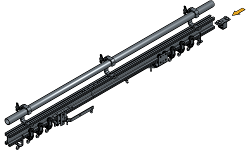
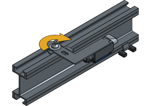
Loosen the channel nuts of the Rope Transmission case and turn them until they fit inside the track profile.
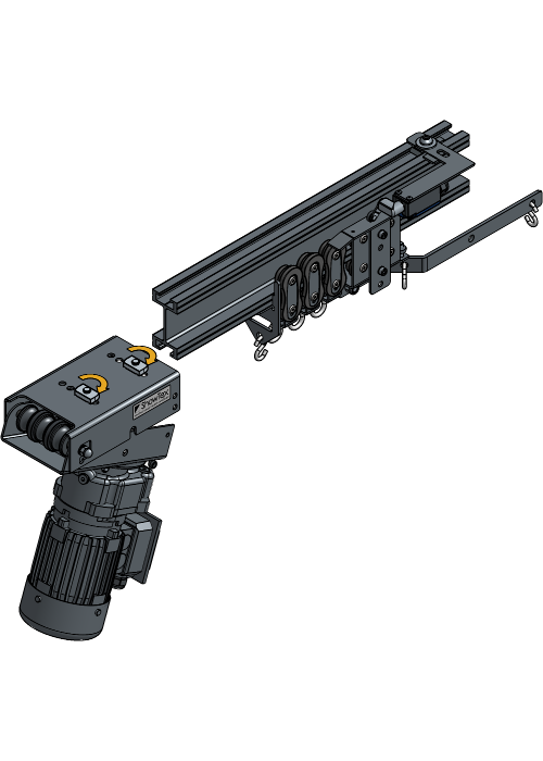
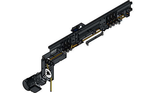
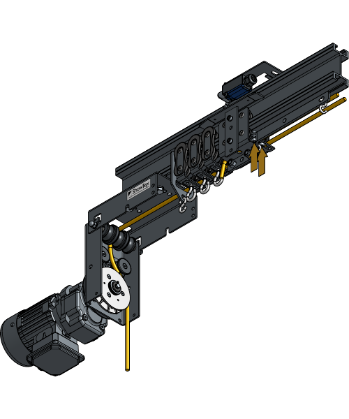
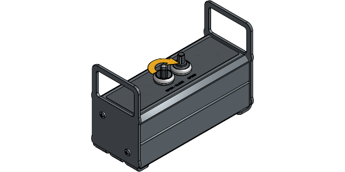
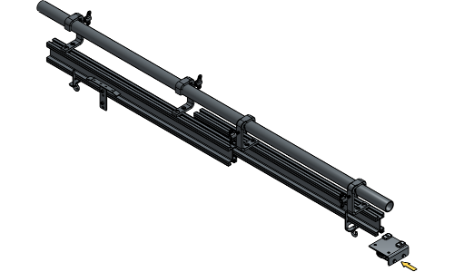
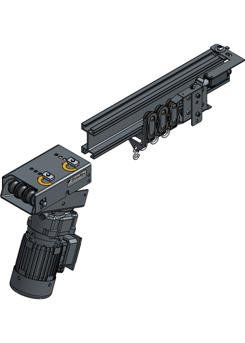
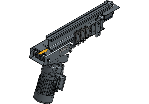
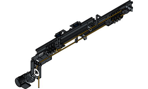
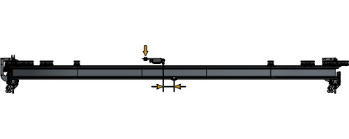
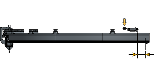
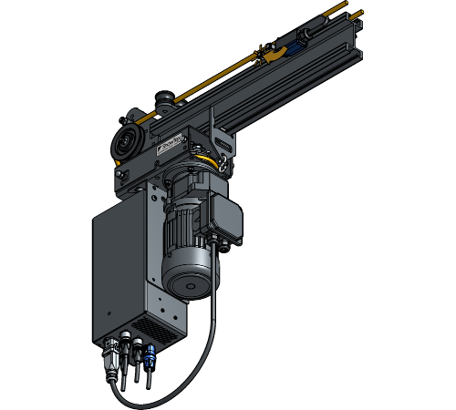
Insert the Rope Drive at the end of the track and tighten the bolts to secure the channel nuts.
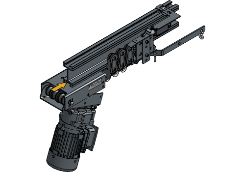
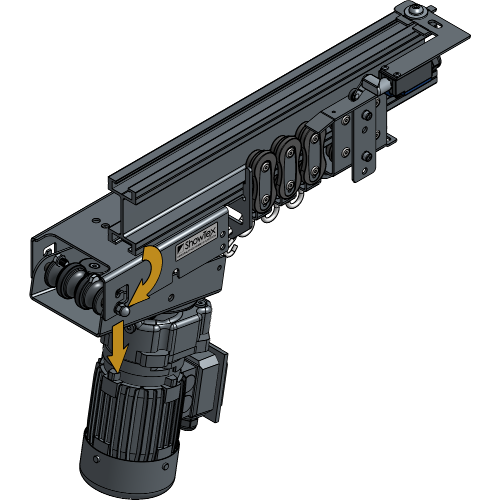
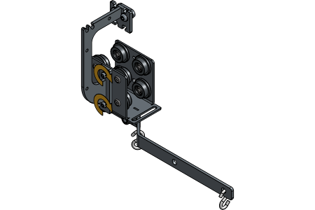
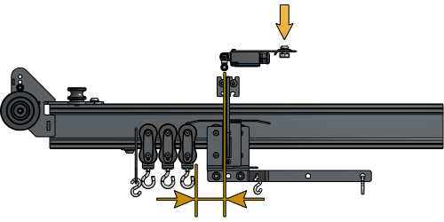
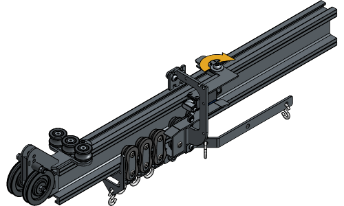
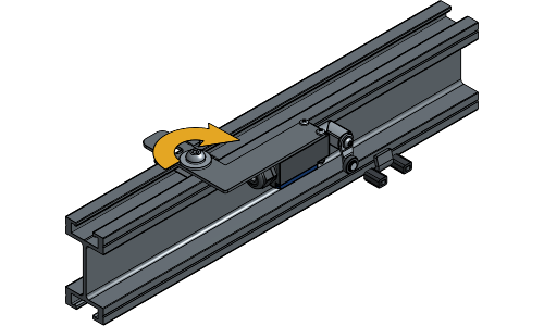
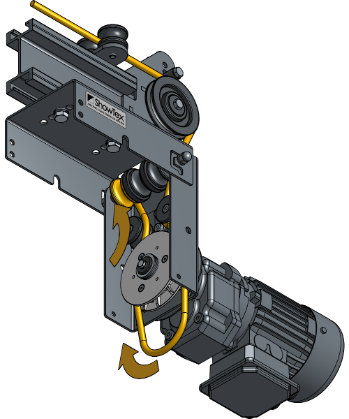
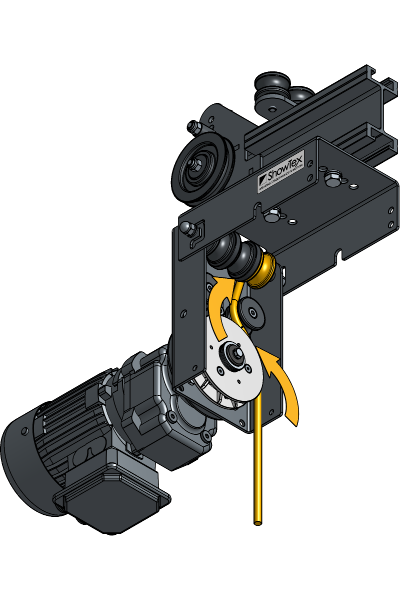
Place the Rope Transmission in the lowest positioning hole.
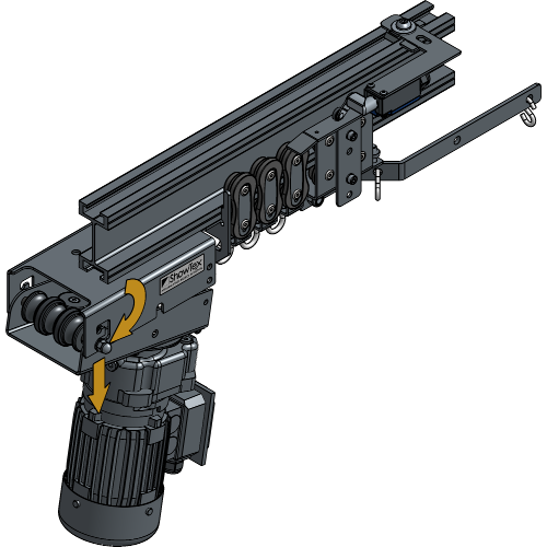
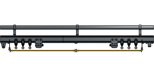
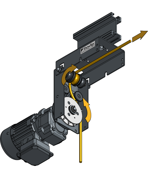
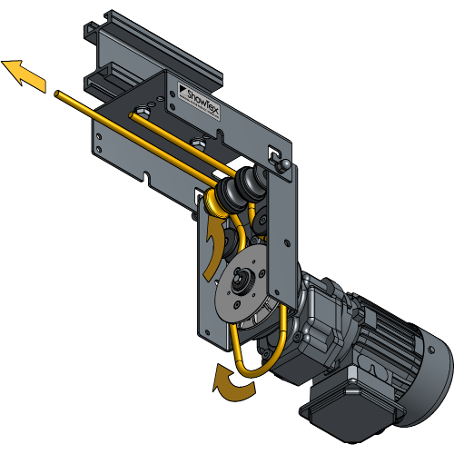
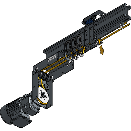
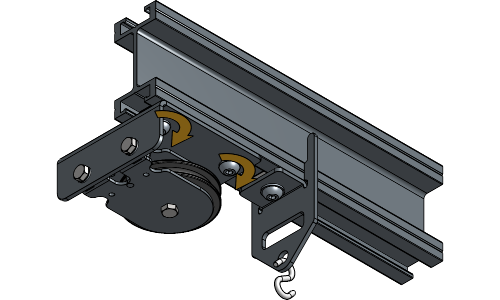
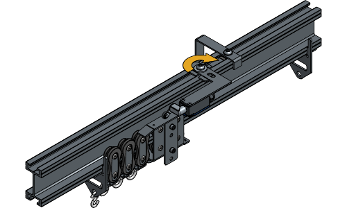
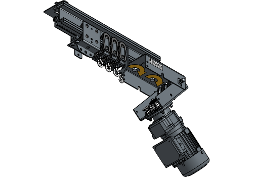
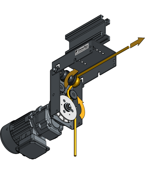
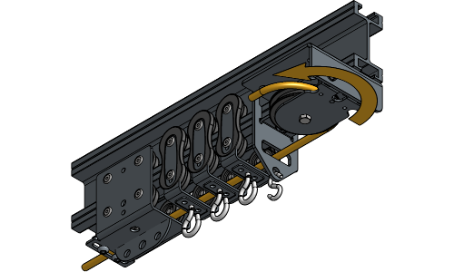
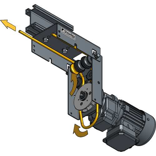
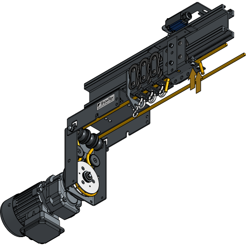
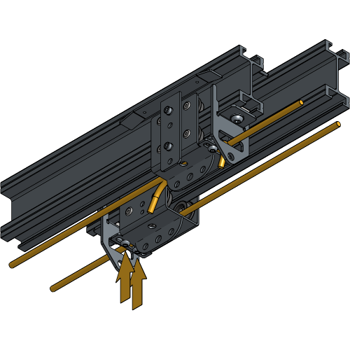
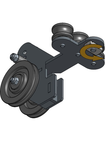
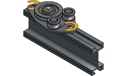
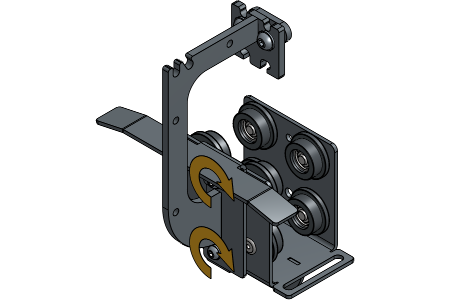
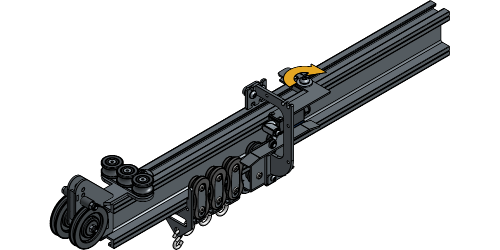
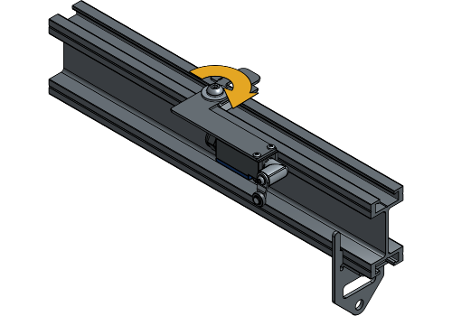
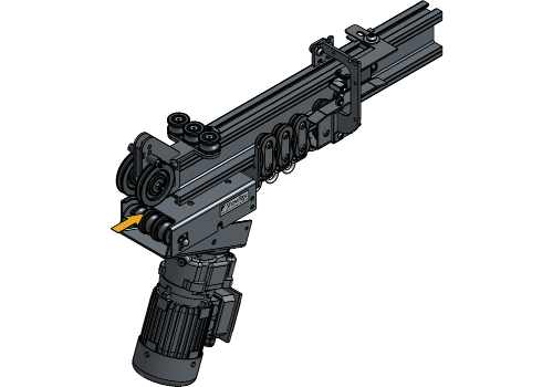
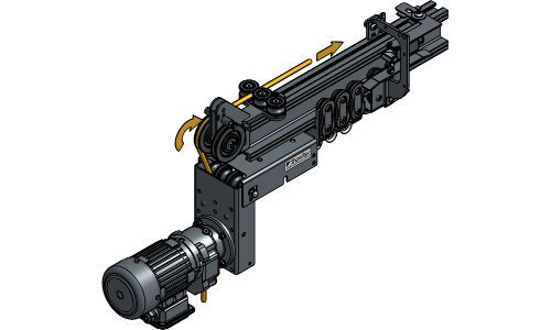
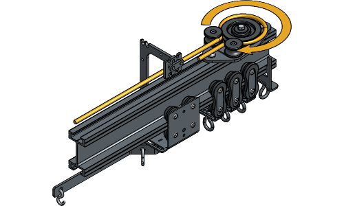
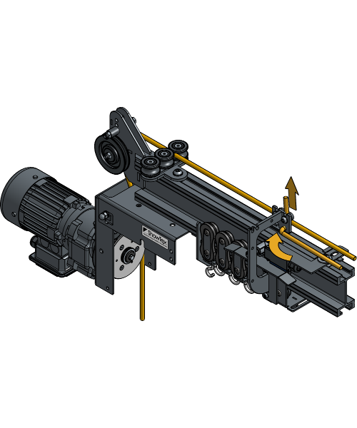
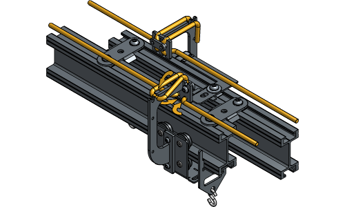
Guide the rope around the backside of the big wheel, around the second vertical wheel.
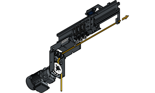
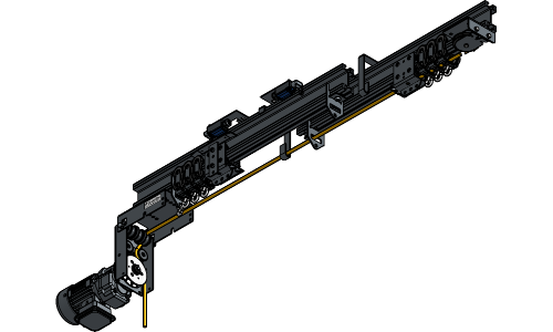
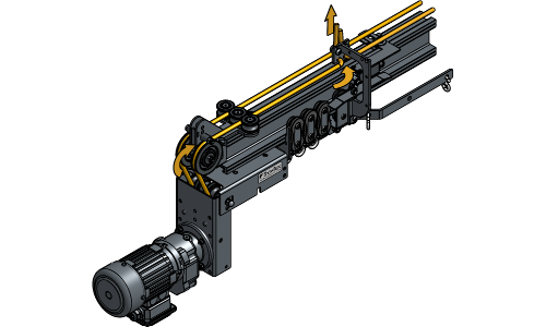
Guide the rope through all End Stops, Runners and Carriers.
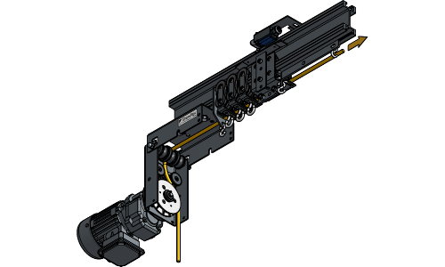
Guide the rope through the Return Pulley and back through the End Stop, Runners and Carriers. End at the Carrier that is closest to the Rope Drive.
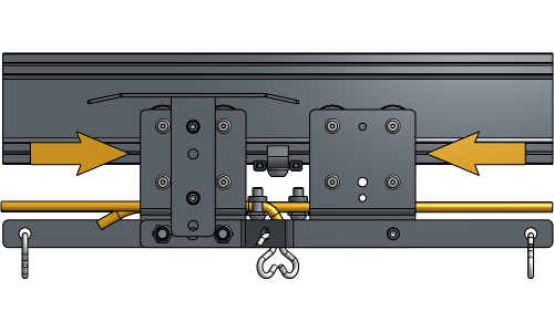
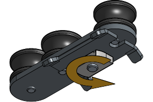
Clamp the first rope end in the rope clamp of that Carrier.
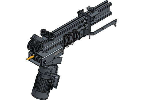
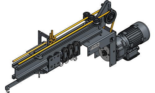
Guide the second rope end around the front side of the big wheel, around the first vertical wheel.
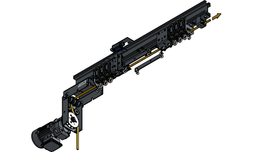
Guide the second rope end through the End Stop and Runners, and stop at the same Carrier where the first rope end is clamped.
Make sure the rope is tight, but leave some slack to be able to clamp the second rope end afterwards. Clamp the second rope end in the same rope clamp where the first rope end is clamped.
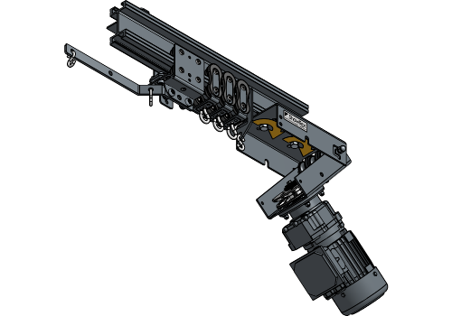
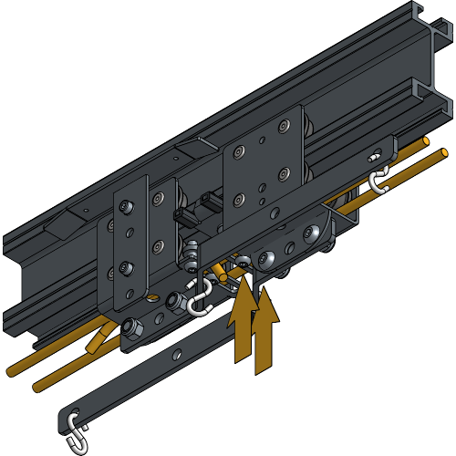
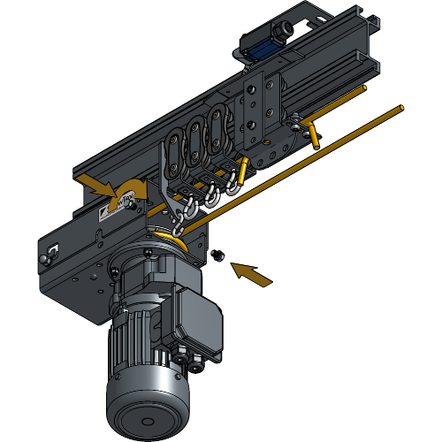
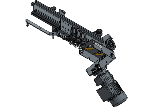
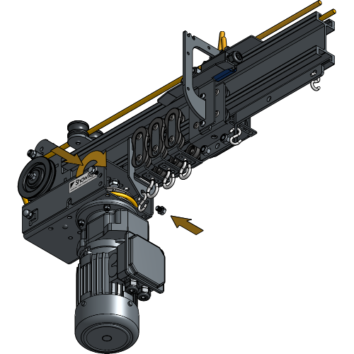
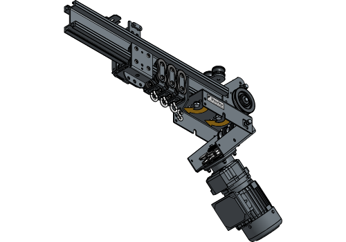
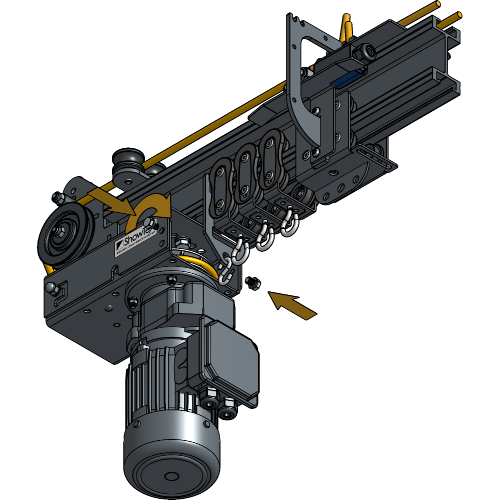
Close the Rope Transmission case and fasten the bolts to secure it.
Closing the Rope Transmission case should add more tension to the rope. If the rope is too tight or isn’t tight enough, readjust it accordingly in the Rope Clamps of the Carriers.
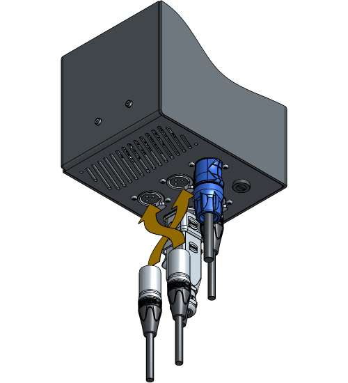
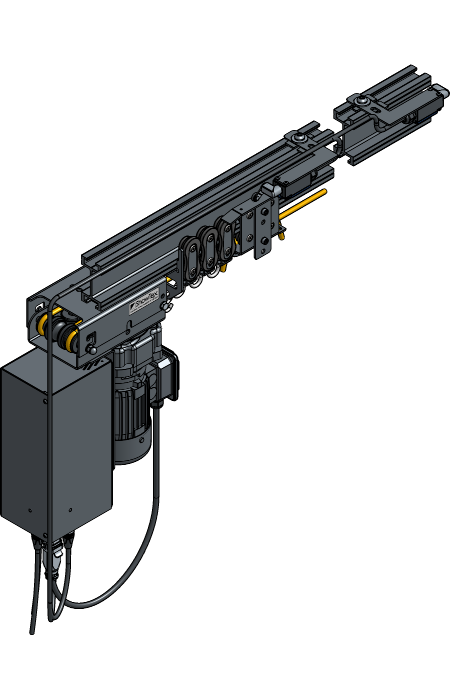
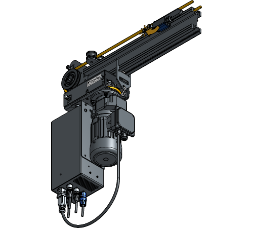
Plug in all cables according to the electrical scheme of the Rope Drive Lite or the electrical scheme of the Rope Drive Standard.
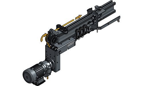
Manually engage the Limit Switch closest to the motor until you hear a click, and operate the motor to close the curtain.
If the carrier does not move towards the middle of the track, switch the cables of the “open” and “close” connection of the Limit Switches on the motor. If the Carrier moves towards the middle of the track, go to the next step.
If you have a central opening, operate the motor to align both Carriers at the Flat End Stop.
Clamp the other side of the rope in the rope clamp of the second Carrier and tighten the screws.
Your Rope Drive for Straight Single Track is now completely installed!
For further installation steps of your ShowTrack, go to Installing the Curtain.
Secure the Limit Switch Ski on the Carrier that will be closest to the motor. The spacers should face the body of the Carrier.
Loosen the channel nut of the End Stops, and turn it until it fits inside the track profile.
Insert one End Stop into the track profile at the outer end of both tracks with the plate directed towards the middle at about 15 cm from the end of the track and tighten the socket screw.
Loosen the channel nuts of the Return Pulley until they fit inside the track profile.
Insert the Return Pulley at the end of the other track next to the End Stop and tighten the socket screw. Rotate the channel nut a quarter turn right and tighten the socket screw.
Insert the number of Runners and Master Carriers on both tracks that are needed for your track system. To know the right number of Runners, refer to the chapter Determining the Number of Runners.
Insert two End Stops the same way at the overlap of the track.
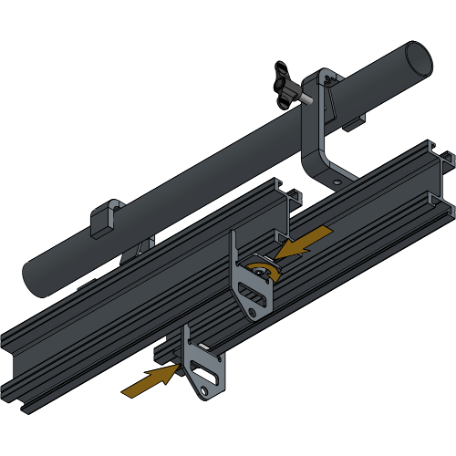
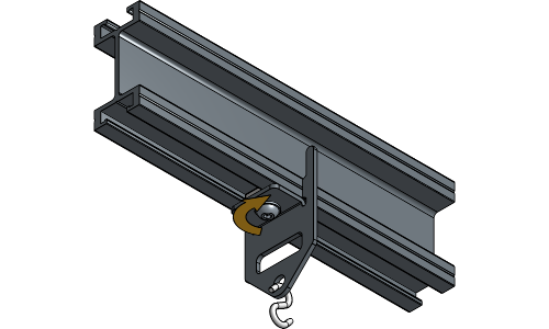
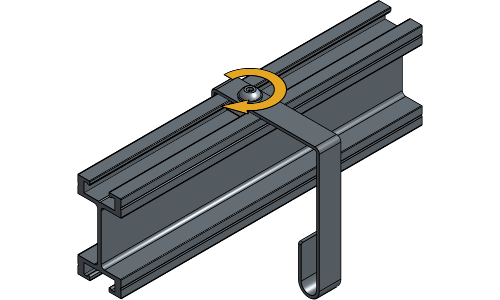
Loosen the channel nut of the Rope Pickups, and turn it until it fits inside the track profile.
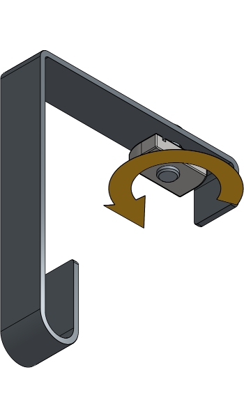
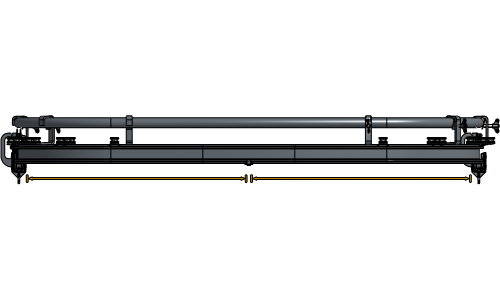
Insert a Rope Pickup every 3 m of a hanging rail to support the rope.
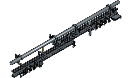
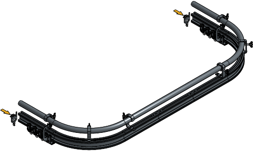
There is one half of the track without support to pick up the rope in a Double Track setup. The End Stops in the middle of the track serve as a support point, after that, a Rope Pickup must be provided every 3 m where the rope hangs freely. It is important that the rope gets this support, otherwise your setup will not work optimally.
The following steps are for a setup with a standard 50 kg Master Carrier. When using the 100 kg or 350 kg Master Carrier, the Limit Switch is mounted on top of the plate with the wheel facing down.
When using Scenery or Quick Release Carriers of 100 or 350 kg, the first Limit Switch is placed at 10 cm distance from the first Runner and the second Limit Switch is placed at 12 cm distance from the Flat End Stop.
Slide all Runners and Carriers towards the outer End Stops in an open curtain position.
Loosen the channel nuts of the Limit Switches.
Bend the outer lip from both Limit Switch Plates about 30° towards the channel nut. This will stabilize the Limit Switch when mounted.
Place the first Limit Switch with the wheel at 7 cm distance from the first Runner and tighten the channel nut.
Place the second Limit Switch with the wheel at 9 cm from the End Stop in the middle of the Track and tighten the channel nut.
Loosen and remove the bolts of the Rope Transmission.
Remove the channel nuts and place them in the second hole of the Rope Transmission.
Loosen the channel nuts of the Rope Transmission case and turn them until they fit inside the track profile.
Insert the Rope Drive at the end of the track and tighten the bolts to secure the channel nuts.
Place the Rope Transmission in the lowest positioning hole.
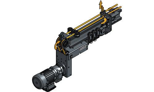
Guide the rope around the backside of the big wheel, around the third vertical wheel.
Guide the rope through all End Stops, Runners and Carriers of this part of the track.
Guide the rope through the Return Pulley and back through the End Stop, Runners and Carriers at the opposite part of the track. End at the Carrier that is closest to the Rope Drive.
Clamp the first rope end in the rope clamp of that Carrier.
Guide the second rope end around the front side of the big wheel, around the first vertical wheel.
Guide the second rope end through the End Stop and Runners, and stop at the same Carrier where the first rope end is clamped.
Make sure the rope is tight, but leave some slack to be able to clamp the second rope end afterwards. Clamp the second rope end in the same rope clamp where the first rope end is clamped.
Close the Rope Transmission case and fasten the bolts to secure it.
Closing the Rope Transmission case should add more tension to the rope. If the rope is too tight or isn’t tight enough, readjust it accordingly in the Rope Clamps of the Carriers.
Plug in all cables according to the electrical scheme of the Rope Drive Lite or the electrical scheme of the Rope Drive Standard.
Manually engage the Limit Switch closest to the motor until you hear a click and operate the motor to close the curtain.
If the carrier does not move towards the middle of the track, switch the cables of the “open” and “close” connection of the Limit Switches on the motor. If the Carrier moves towards the middle of the track, go to the next step.
Operate the motor to align both Carriers at the End Stops.
Clamp the other side of the rope in the rope clamp of the second Carrier and tighten the screws.
Your Rope Drive for Straight Double Track is now completely installed!
For further installation steps of your ShowTrack, go to Installing the Curtain.
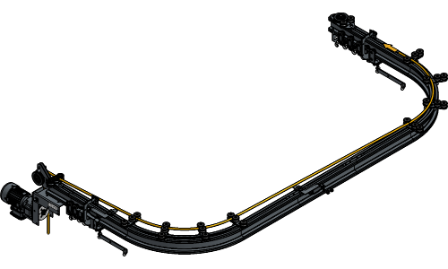
Lay the Overlap Arms in the correct “left before right” position.
Secure the Overlap Arm to the Carrier with bolts in the first and third hole of the Overlap Arm.
Place an S-Hook in the first and last hole of the Overlap Arm that are available of both Master Carriers.
Secure the Limit Switch Ski on the Carrier that will be closest to the motor on the same side as the Overlap Arm. The spacers should face the body of the Carrier.
Secure a Rope Clamp on the other Carrier if you have a central opening.
Insert the number of Runners and Master Carriers that are needed for your track system. To know the right number of Runners, refer to the chapter Determining the Number of Runners.
The Master Carriers and Runners need to be inserted at the two ends of the track in the correct way for the Master Carriers to be able to pass.
Loosen the channel nut of the End Stops, and turn it until it fits inside the track profile.
Insert both End Stops into the track profile at the end of the track with the plate directed towards the middle. Rotate the Channel Nuts a quarter turn right and tighten the socket screws.
Loosen the channel nut of the Head Pulley until it fits inside the track profile.
Insert the Head Pulley at the end of the track on the side where the rope needs to be operated. Rotate the channel nut a quarter turn right and tighten the socket screw.
Loosen the channel nuts of the Return Pulley until they fit inside the track profile.
Insert the Return Pulley at the end of the track next to the End Stop. Rotate the channel nuts a quarter turn right and tighten the socket screws.
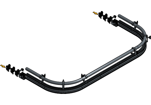
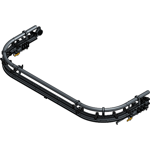
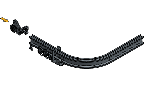
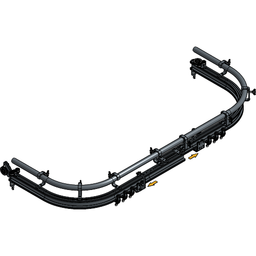
Loosen the Channel nut of the Curve Rope Guides until it fits inside the track profile and insert one every 3 m at each side of the track. Make sure they are oriented for the Master Carriers to be able to pass.
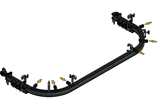
In the curves, there should be a Curve Rope Guide at the beginning and end of the curve and every 30 cm in between.
If you have a central opening in your ShowTrack system, insert a Flat End Stop at the place of overlap with the correct amount of Runners at each side.
The following steps are for a setup with a standard 50 kg Master Carrier. When using the 100 kg or 350 kg Master Carrier, the Limit Switch is mounted on top of the plate with the wheel facing down.
When using Scenery or Quick Release Carriers of 100 or 350 kg, the first Limit Switch is placed at 10 cm distance from the first Runner and the second Limit Switch is placed at 12 cm distance from the Flat End Stop.
Slide all Runners and Carriers towards the outer End Stops in an open curtain position.
Loosen the channel nuts of the Limit Switches.
Bend the outer lip from both Limit Switch Plates about 30° towards the channel nut. This will stabilize the Limit Switch when mounted.
Place the first Limit Switch with the wheel at 7 cm distance from the first Runner and tighten the channel nut.
Place the second Limit Switch with the wheel at 9 cm from the Flat End Stop and tighten the channel nut.
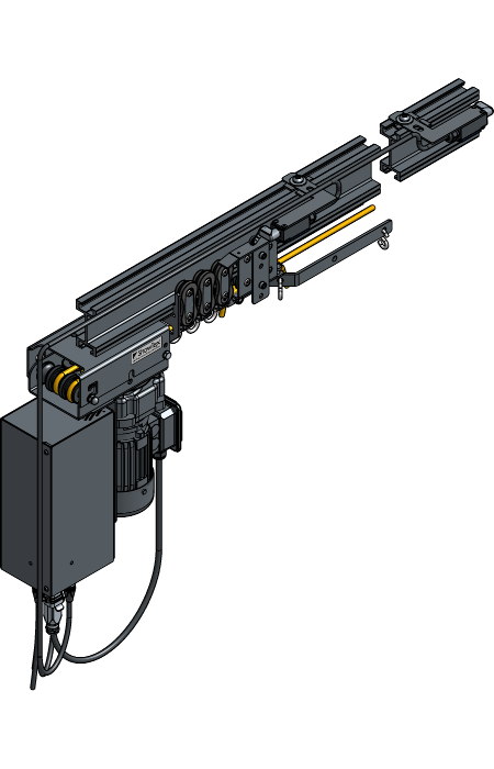
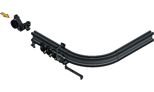
Loosen the channel nuts of the Rope Transmission case and turn them until they fit inside the track profile.
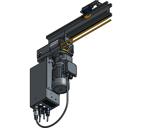
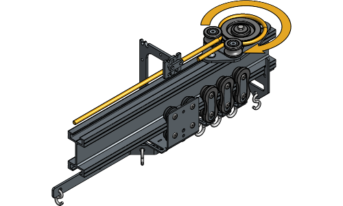
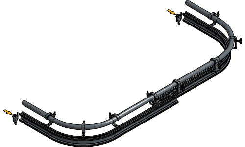
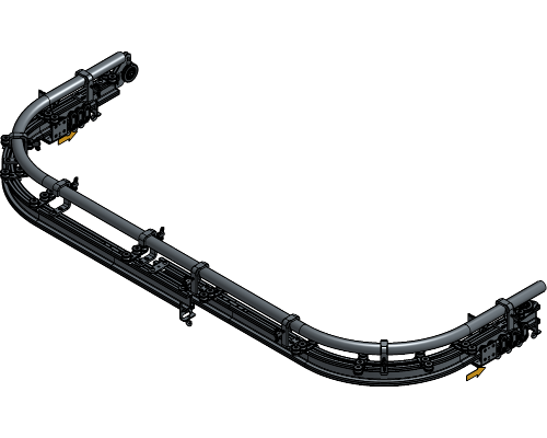
Insert the Rope Drive at the end of the track with the wheels in line to the Head Pulley and tighten the bolts to secure the channel nuts.
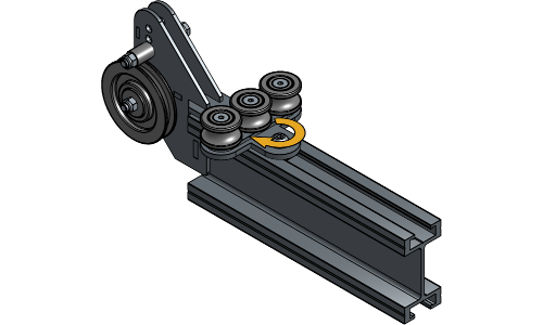
Guide the rope around the backside of the big wheel, around the third vertical wheel.

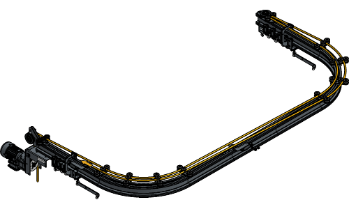
Guide the rope through the backside of the Head Pulley and all Curve Rope Guides towards the Return Pulley.
Guide the rope through the Return Pulley and towards the carrier that is closest to the motor.
Guide the rope through the rope clamp of that carrier and clamp it temporarily.
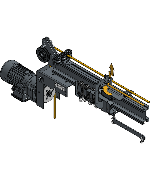
Guide the second rope end through the backside of the big wheel, around the first vertical wheel.
Clamp the other side of the rope in the rope clamp of the second Carrier and tighten the screws.
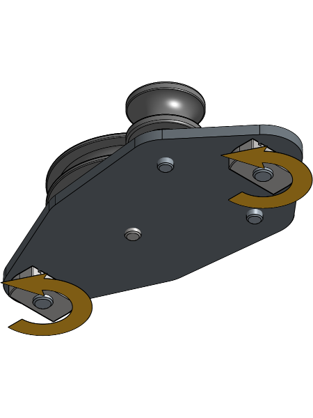
Close the Rope Transmission case and fasten the bolts to secure it.
Closing the Rope Transmission case should add more tension to the rope. If the rope is too tight or isn’t tight enough, readjust it accordingly in the Rope Clamps of the Carriers.
Plug in all cables according to the electrical scheme of the Rope Drive Lite or the electrical scheme of the Rope Drive Standard.
Manually engage the Limit Switch closest to the motor until you hear a click and operate the motor to close the curtain.
If the carrier does not move towards the middle of the track, switch the cables of the “open” and “close” connection of the Limit Switches on the motor. If the Carrier moves towards the middle of the track, go to the next step.
If you have a central opening, operate the motor to align both Carriers at the Flat End Stop.

Clamp the other side of the rope in the rope clamp of the second Carrier and tighten the screws.
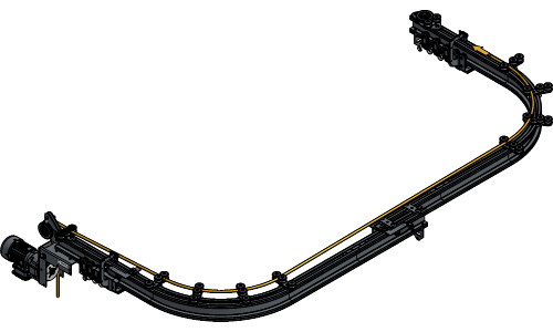
Your Rope Drive for Curved Single Track is now completely installed!
For further installation steps of your ShowTrack, go to Installing the Curtain.
Secure the Limit Switch Ski and the Rope Clamp on the Carrier that will be closest to the motor. The spacers should face the body of the Carrier.
Secure a Rope Clamp on the other Carrier.
Loosen the channel nut of the End Stops, and turn it until it fits inside the track profile.
Insert one End Stop into the track profile at the outer end of both tracks with the plate directed towards the middle and tighten the socket screw.
Loosen the channel nut of the Head Pulley until it fits inside the track profile.
Insert the Head Pulley at the end of the track on the side where the rope needs to be operated. Rotate the channel nut a quarter turn right and tighten the socket screw.
Loosen the channel nuts of the Return Pulley until they fit inside the track profile.
Insert the Return Pulley at the other end of the track. Rotate the channel nuts a quarter turn right and tighten the socket screws.

Insert the number of Runners and Master Carriers that are needed for your track system. To know the right number of Runners, refer to the chapter Determining the number of Runners.
Insert two End Stops the same way at the overlap of the track.
Loosen the Channel nut of the Curve Rope Guides until it fits inside the track profile and insert one every 3 m at each side of the track. Make sure they are oriented for the Master Carriers to be able to pass.
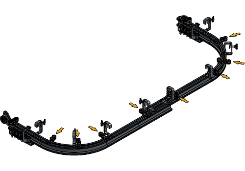
In the curves, there should be a Curve Rope Guide at the beginning and end of the curve and every 30 cm in between.
The following steps are for a setup with a standard 50 kg Master Carrier. When using the 100 kg or 350 kg Master Carrier, the Limit Switch is mounted on top of the plate with the wheel facing down.
When using Scenery or Quick Release Carriers of 100 or 350 kg, the first Limit Switch is placed at 10 cm distance from the first Runner and the second Limit Switch is placed at 12 cm distance from the Flat End Stop.
Slide all Runners and Carriers towards the outer End Stops in an open curtain position.
Loosen the channel nuts of the Limit Switches.
Bend the outer lip from both Limit Switch Plates about 30° towards the channel nut. This will stabilize the Limit Switch when mounted.
Place the first Limit Switch with the wheel at 7 cm distance from the first Runner and tighten the channel nut.
Place the second Limit Switch with the wheel at 9 cm from the End Stop in the middle of the Track and tighten the channel nut.
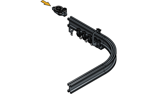
Loosen and remove the bolts of the Rope Transmission.
Loosen the channel nuts of the Rope Transmission case and turn them until they fit inside the track profile.
Insert the Rope Drive at the end of the track with the wheels in line to the Head Pulley and tighten the bolts to secure the channel nuts.
Guide the rope around the backside of the big wheel, around the third vertical wheel.
Guide the rope through the backside of the Head Pulley and all Curve Rope Guides towards the Return Pulley.
Guide the rope through the Return Pulley and towards the carrier that is closest to the motor.
Guide the rope through the rope clamp of that carrier and clamp it temporarily.
Guide the second rope end through the backside of the big wheel, around the first vertical wheel.

Clamp the other side of the rope in the rope clamp of the second Carrier and tighten the screws.
Close the Rope Transmission case and fasten the bolts to secure it.
Closing the Rope Transmission case should add more tension to the rope. If the rope is too tight or isn’t tight enough, readjust it accordingly in the Rope Clamps of the Carriers.
Plug in all cables according to the electrical scheme of the Rope Drive Lite or the electrical scheme of the Rope Drive Standard.
Manually engage the Limit Switch closest to the motor until you hear a click and operate the motor to close the curtain.
If the carrier does not move towards the middle of the track, switch the cables of the “open” and “close” connection of the Limit Switches on the motor. If the Carrier moves towards the middle of the track, go to the next step.
Operate the motor to align both Carriers at the End Stops.
Clamp the other side of the rope in the rope clamp of the second Carrier and tighten the screws.
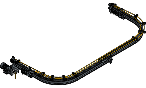
Your Rope Drive for Curved Double Track is now completely installed!
For further installation steps of your ShowTrack, go to Installing the Curtain.
For more technical assistance, please contact your local ShowTex
office.
The address and contact information can be found on our website:
www.showtex.com