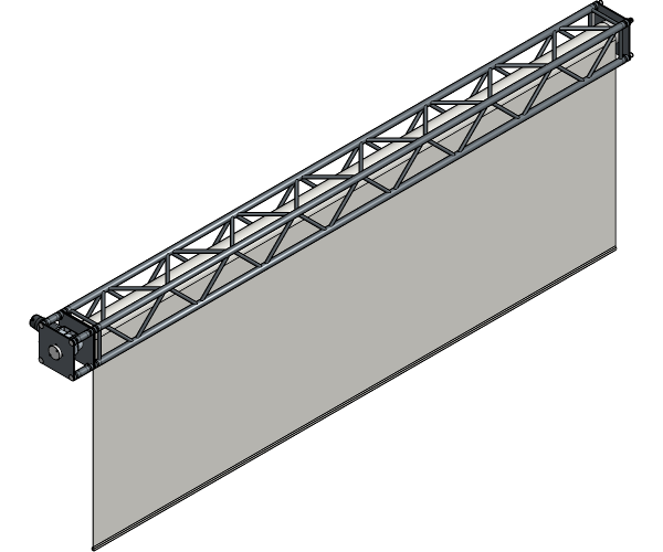
HiSpeed RollUp
Truss Roller with HiSpeed Motor 3000
Installation Manual
Installation Manual
No part of this publication may be duplicated or edited in any form or by any means, including any type of electronic or mechanical method without prior written permission from ShowTex.
ShowTex and its employees are fully aware of their task to provide a reliable edition of this document. Nevertheless, they cannot accept any form of liability for the direct or indirect consequences of imperfections that might remain in this edition. The material in this manual is subject to change without notice.
ShowTex warrants that its mechanical and technical products, when delivered in new condition, in original packing, sold directly and used in normal conditions are free from any defects in manufacturing, materials and workmanship. For more information about your local warranty terms, please check our website or contact your local ShowTex office.
All products from the ShowTex Rental range are supposed to be returned in the same state as they were rented. Please treat our products with care, allowing the next user to enjoy the products as much as you did. The rented products are internally checked according to the general rental conditions. Be sure to check our rental guidelines on our website before installing and using this product: ShowTex rental guidelines
Read and understand this user manual before installing and or operating the system. Failure to follow the instructions in this document could result in serious injury!
Following the guidelines of this manual will reduce the risk of damaging the equipment or injuring yourself and the people around you. Nevertheless, ShowTex cannot be held accountable for any use or misuse of the equipment and supplies.
Damage to the system caused by any other method of installation than the one shown in this manual can only be repaired or fixed at the customer’s expense.
As a result of the above warning, any ShowTex product must be installed and operated by a qualified technician who knows its capabilities as well as its limitations.
In case you are uncertain about the eligibility of any hardware in your product, please get in touch with your local ShowTex office to receive additional guidance.
Thank you for choosing for ShowTex and purchasing one of our products. We want to ensure that your experience is as smooth and safe as possible, so we kindly request that you take a few moments to carefully read this manual before installing your new system.
This manual contains important information that will help you comply with health and safety regulations, as well as provide guidance on how to safely install, operate and maintain your product. Our team has taken great care to ensure that this manual is easy to understand and follow, using straightforward language and clear illustrations.
If you have any questions or concerns regarding the installation or use of your product, please feel free to contact your local ShowTex office. Our knowledgeable team members are always available to assist you and answer any questions you may have.
Periodic, regularly scheduled maintenance inspections are essential for every product. Each system contains components that must be inspected, adjusted, maintained, or replaced over time. Establishing a consistent maintenance routine ensures long-term safety, reliability, and optimal performance.
Please follow the steps outlined in the Care & Maintenance schedule provided for this product. These steps represent the minimum required maintenance program.
| Article number | Colour | Weight | Length |
|---|---|---|---|
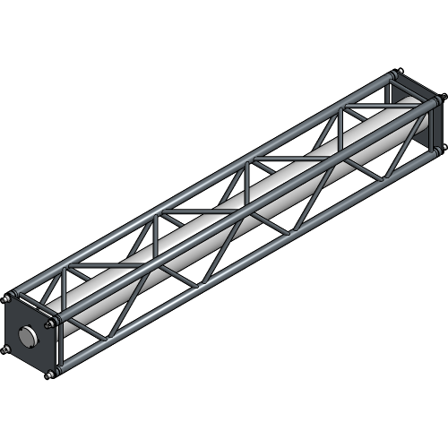
| 8140 3115 3007 | Black | 125.00 kg | 3.00 m |
| 8140 3115 6007 | Black | 175.00 kg | 6.00 m |
| 8140 3115 9007 | Black | 225.00 kg | 9.00 m |
| Article number | Colour | Weight | Cable length |
|---|---|---|---|
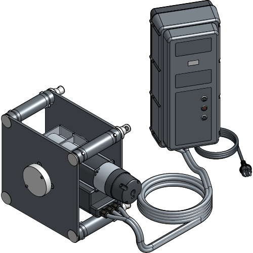
| 8140 3112 1037 | Black | 50.00 kg | 21.00 m |

| Article number | Colour | Weight | Length |
|---|---|---|---|
| 8140 3120 3007 | Black | 4.00 kg | 3.00 m |
| 8140 3120 6007 | Black | 8.00 kg | 6.00 m |
| 8140 3120 9007 | Black | 12.00 kg | 9.00 m |
| Article number | Colour | Weight |
|---|---|---|
| 8140 2247 0124 | Aluminium | 0.18 kg |
| Article number | Colour | Weight |
|---|---|---|
| 8140 2247 0224 | Aluminium | 0.23 kg |
| Article number | Colour | Weight |
|---|---|---|
| 8140 2247 0004 | Aluminium | 0.11 kg |
| Article number | Colour | Weight |
|---|---|---|
| 8140 3116 3027 | Aluminium | 0.50 kg |
| Article number | Colour | Weight |
|---|---|---|
| 8140 2247 0014 | Aluminium | 0.04 kg |
| Article number | Colour | Weight |
|---|---|---|
| 8140 2253 0001 | Aluminium | 0.05 kg |

| Article number | Colour | Weight |
|---|---|---|
| 8140 9999 0007 | Red | 0.05 kg |

| Article number | Colour | Weight |
|---|---|---|
| 8140 0766 0030 | Black | 5.75 kg |

| Article number | Colour | Weight | Length |
|---|---|---|---|
| 8160 0915 0257 | Black | 3.42 kg | 25.00 m |

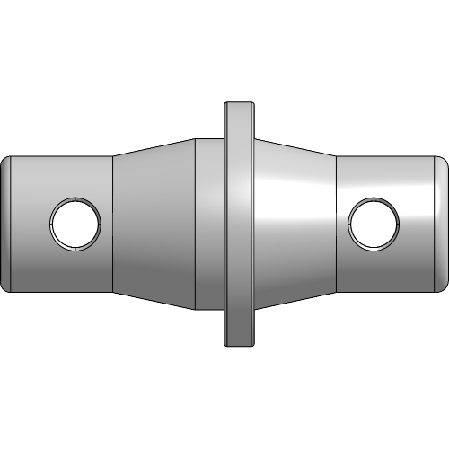
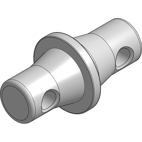
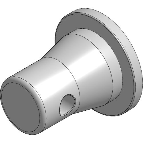
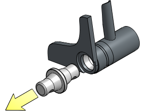
Conical Couplers Truss-Roll are used to connect a Truss Roller to the HiSpeed Motor 8000. The Truss-Roll Couplers are asymmetrical as one side has a conical and a cylindrical shape and mates with the truss. The other side is fully conical shaped and mates with the truss roller.

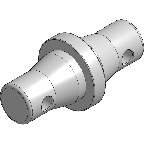
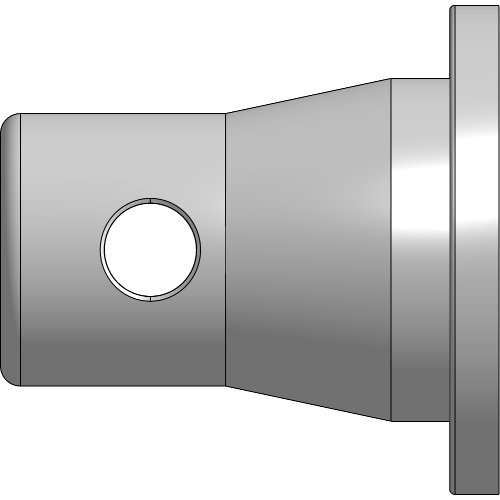
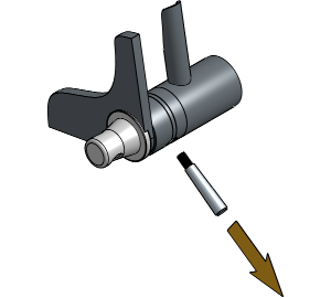
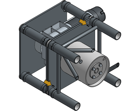
Conical Couplers Roll-Roll are used either to connect two Truss Rollers, a Truss Roller and the HiSpeed Motor 3000 or the Angled Transmission. The Roll-Roll Couplers are symmetrically shaped with on both sides a conical and cylindrical shape.
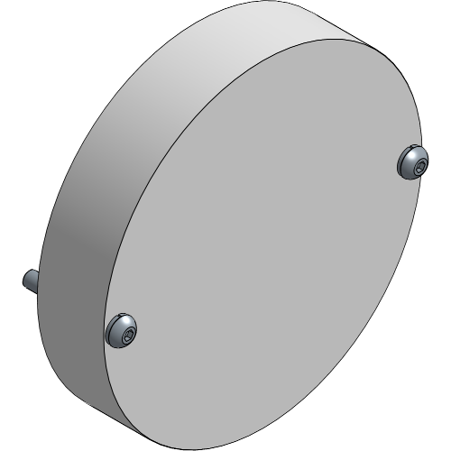
Conical End Pieces are used for protection of the Truss and are removed when the Truss Roller gets coupled. For transport the Conical End Pieces need to be re-inserted at all times.
If the HiSpeed setup was delivered assembled, go to chapter Rigging the Truss Roller.
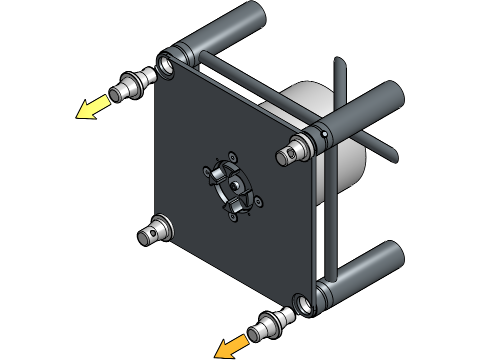
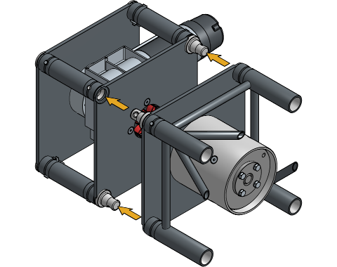
The motors and rollers always need at least 2 Conical Couplers or End Pieces in place. Never remove 4 Conical Couplers or Conical End Pieces of a motor or roller simultaneously as this will result in the side plate to detach and roller to fall apart.
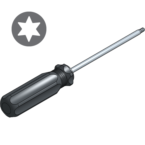
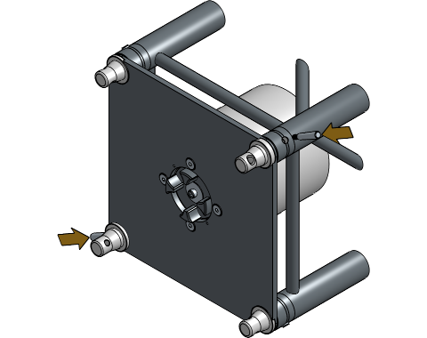
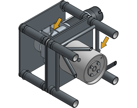
Remove the bottom right and upper left Safety Clips out of the Pins of the motor.
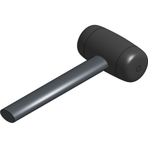
Hammer the bottom right and upper left Pins out of the motor.
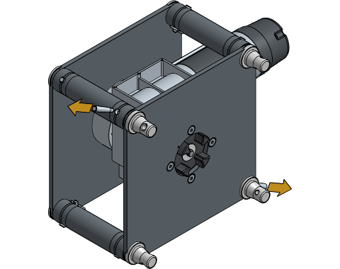
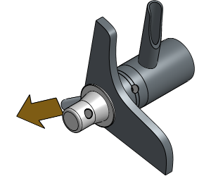
Remove the bottom right and upper left Roll-Roll Conical Couplers out of the motor.
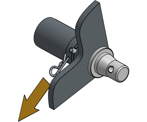
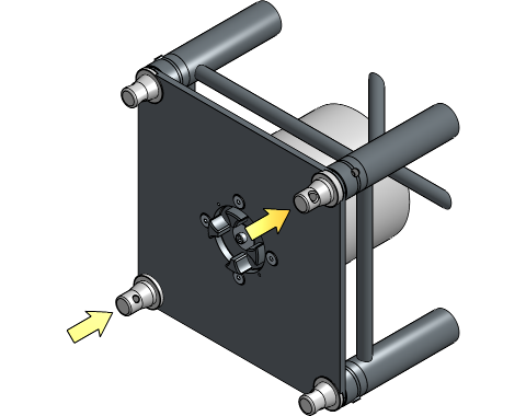
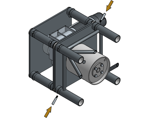
Unfasten and remove the bottom left and upper right Safety Nuts from the Pins of the Truss Roller.
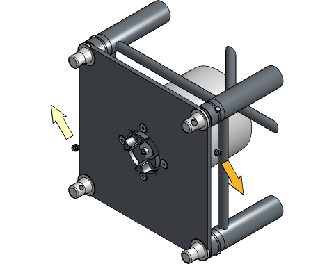
Hammer the bottom left and upper right Pins out of the Truss Roller.
It is advised to screw on a separate nut on the Pins not to damage the thread. Hammering on the Pin directly can damage the thread, and hammering on the Safety Nut can damage the bearing.
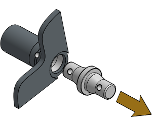
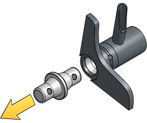
Remove the bottom left and upper right Truss-Roll Conical Couplers out of the Truss Roller.
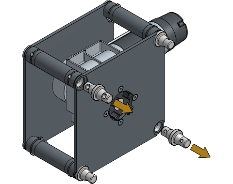
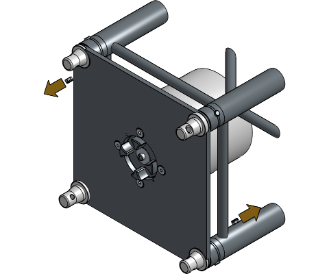
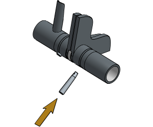
Insert the Roll-Roll Conical Couplers you removed from the motor in the empty bottom left and upper right holes of the Truss Roller.
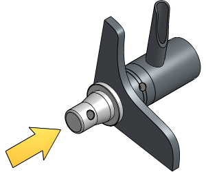
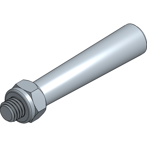
Hammer a Pin with thread in the bottom left and upper right holes of the Truss Roller.
Fasten a Safety Nut on the bottom left and upper right Pins of the Truss Roller.
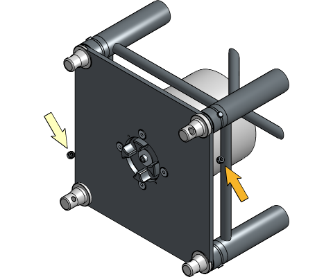
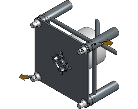
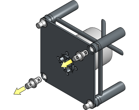
Remove the bottom right and upper left Safety Nuts from the Pins of the Truss Roller.

Hammer the bottom right and upper left Pins out of the Truss Roller.

Remove the bottom right and upper left Truss-Roll Conical Couplers out of the Truss Roller.
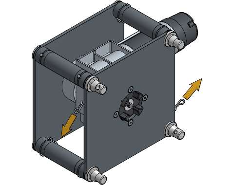
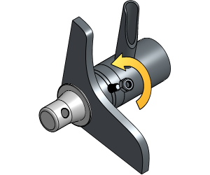
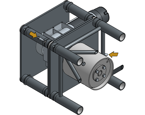
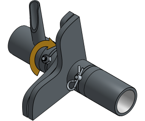
Place the Coupling Spider on the coupling jaw of the motor.
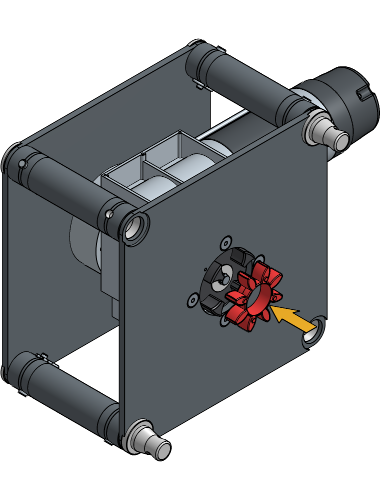
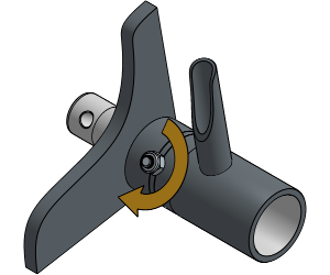
Align the coupling jaw of the Truss Roller with the coupling jaw of the motor and insert the Conical Couplers into the Truss Roller.
The coupling jaw of the motor and Truss Roller need to be aligned in order to couple them. If they are not aligned, rotate the Truss Roller until they are.
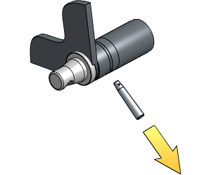
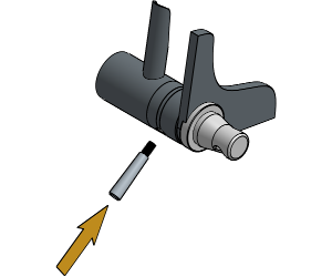
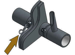
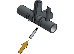
Hammer a Pin with the hole lined up vertically in the empty holes of the motor a Pin with thread in the empty holes of the Truss Roller.
Insert the Safety Clips in the Pins of the motor.
Hammer a Pin with thread in the empty holes of the Truss Roller
Fasten a Safety Nut on the Pins of the Truss Roller.
Provide the rigging points that are required for your setup.
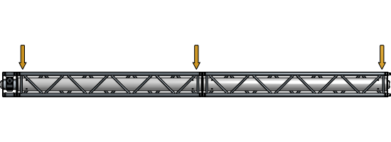
A rigging point must be provided at each truss junction. For more information about the correct rigging points for each setup, consult the Technical Data Sheet.
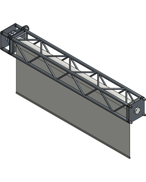
If the HiSpeed setup is delivered assembled, the screen is already attached to the Truss Roller and you will only need to use the soft limit steps to make adjustments. Performing the following steps will help to set your high and low limit where the screen needs to stop.
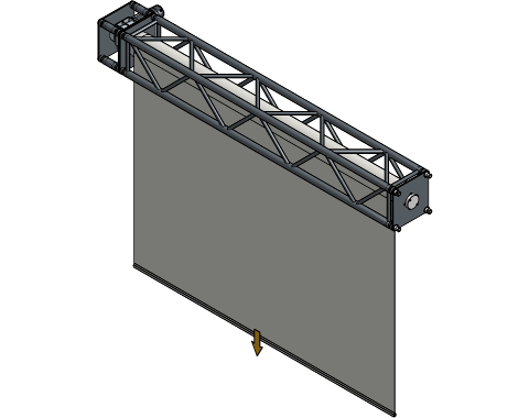
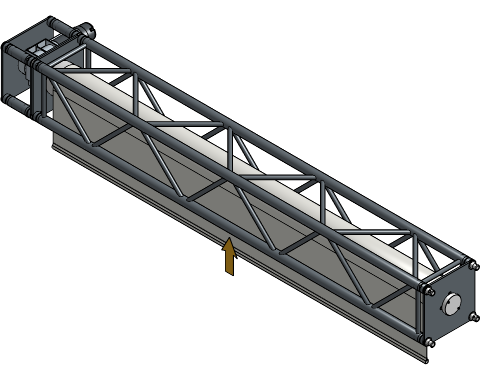
Attach the screen onto the roller.
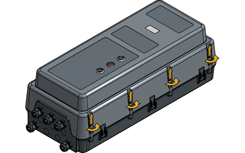
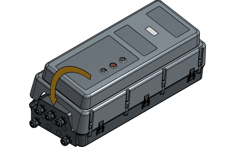
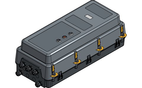
Unfasten the screws on both sides of the Control Box and open the top cover.
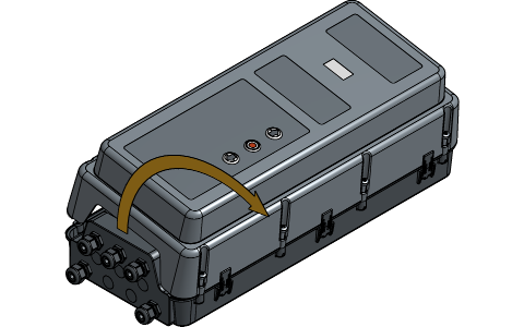
Hold the P button until the screen
says ADJUSTMENT STANDBY.

Hold the + or
- button to move the screen to the desired
“low” position. There must be at least two full turns on the roller.
Hold the P and
- button at same time to store the current
location as the “low” limit. The screen should say
ADJUSTMENT STORAGE DOWN.

Hold the + button to move the
screen to the desired “high” position.
Hold the P and
+ button at same time to store the current
location as the “high” limit. The screen should say
ADJUSTMENT STORAGE UP.

Press the P button two times. The
screen should now say
TEACH IN RUN STANDBY.

Hold the ⬆ or
⬇ button on the Control Box to move the
screen up or down until the screen says
AUTOMATIC STANDBY.

Close the top cover and fasten the screws of the Control Box.
Your HiSpeed RollUp Truss Roller setup with HiSpeed Motor 3000 is now completely installed and ready to use!
For more technical assistance, please contact your local ShowTex
office.
The address and contact information can be found on our website:
www.showtex.com