ScreenFrame
0° Corner
Installation manual

Installation manual
No part of this publication may be duplicated or edited in any form or by any means, including any type of electronic or mechanical method without prior written permission from ShowTex.
ShowTex and its employees are fully aware of their task to provide a reliable edition of this document. Nevertheless, they cannot accept any form of liability for the direct or indirect consequences of imperfections that might remain in this edition. The material in this manual is subject to change without notice.
ShowTex warrants that its mechanical and technical products, when delivered in new condition, in original packing, sold directly and used in normal conditions are free from any defects in manufacturing, materials and workmanship. For more information about your local warranty terms, please check our website or contact your local ShowTex office.
All products from the ShowTex Rental range are supposed to be returned in the same state as they were rented. Please treat our products with care, allowing the next user to enjoy the products as much as you did. The rented products are internally checked according to the general rental conditions. Be sure to check our rental guidelines on our website before installing and using this product: ShowTex rental guidelines
Read and understand this user manual before installing and or operating the system. Failure to follow the instructions in this document could result in serious injury!
Following the guidelines of this manual will reduce the risk of damaging the equipment or injuring yourself and the people around you. Nevertheless, ShowTex cannot be held accountable for any use or misuse of the equipment and supplies.
Damage to the system caused by any other method of installation than the one shown in this manual can only be repaired or fixed at the customer’s expense.
As a result of the above warning, any ShowTex product must be installed and operated by a qualified technician who knows its capabilities as well as its limitations.
In case you are uncertain about the eligibility of any hardware in your product, please get in touch with your local ShowTex office to receive additional guidance.
Thank you for choosing for ShowTex and purchasing one of our products. We want to ensure that your experience is as smooth and safe as possible, so we kindly request that you take a few moments to carefully read this manual before installing your new system.
This manual contains important information that will help you comply with health and safety regulations, as well as provide guidance on how to safely install, operate and maintain your product. Our team has taken great care to ensure that this manual is easy to understand and follow, using straightforward language and clear illustrations.
If you have any questions or concerns regarding the installation or use of your product, please feel free to contact your local ShowTex office. Our knowledgeable team members are always available to assist you and answer any questions you may have.
| Article number | Colour | Weight | Length |
|---|---|---|---|
| 8800 4103 6007 | Black | 3.00 kg/m | 6.00 m |
| Article number | Colour | Weight | Length |
|---|---|---|---|
| 8800 0007 9997 | Black | 3.00 kg/m | 6.00 m |
| Article number | Colour | Weight |
|---|---|---|
| 8800 4100 0007 | Black | 2.42 kg |
| Article number | Colour | Weight |
|---|---|---|
| 8800 0042 0007 | Black | 1.25 kg |
| Article number | Colour | Weight |
|---|---|---|
| 8800 0041 0107 | Black | 2.80 kg |

| Article number | Colour | Weight |
|---|---|---|
| 8800 0042 0024 | Black | 0.94 kg |
| Article number | Colour | Weight |
|---|---|---|
| 8800 0042 0027 | Black | 3.58 kg |
| Article number | Colour | Weight |
|---|---|---|
| 8800 0042 0047 | Black | 2.07 kg |
| Article number | Colour | Weight |
|---|---|---|
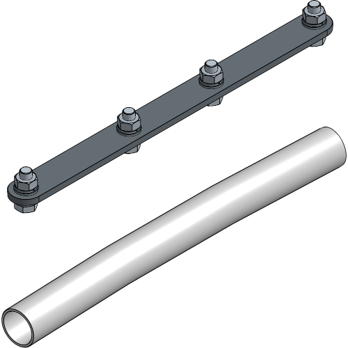
| 8800 0010 0457 | Black | 0.88 kg/m |
| Article number | Colour | Weight |
|---|---|---|
| 8800 0041 0017 | Black | 2.74 kg |
| Article number | Colour | Weight |
|---|---|---|
| 8800 4101 2001 | Black | 0.33 kg |
| Article number | Colour | Weight |
|---|---|---|
| 8840 9600 7231 | Steel | 0.02 kg/m |

| Article number | Colour | Weight | WLL | SF |
|---|---|---|---|---|
| 8800 0674 0117 | Black | 2.48 kg | 285.00 kg | 2:1 |

| Article number | Colour | Weight | WLL | SF |
|---|---|---|---|---|
| 8800 0650 0307 | Black | 0.36 kg | 100.00 kg | 2:1 |

| Article number | Colour | Weight | WLL | SF |
|---|---|---|---|---|
| 8800 0677 0817 | Black | 0.30 kg | 100.00 kg | 2:1 |

| Article number | Colour | Weight | WLL | SF |
|---|---|---|---|---|
| 8800 0041 0024 | Aluminium | 0.23 kg | 100.00 kg | 2:1 |
| Article number | Colour | Weight |
|---|---|---|
| 7641 0013 0007 | Black | 0.02 kg |
| Article number | Colour | Weight |
|---|---|---|
| 7642 0014 0007 | Black | 0.02 kg |

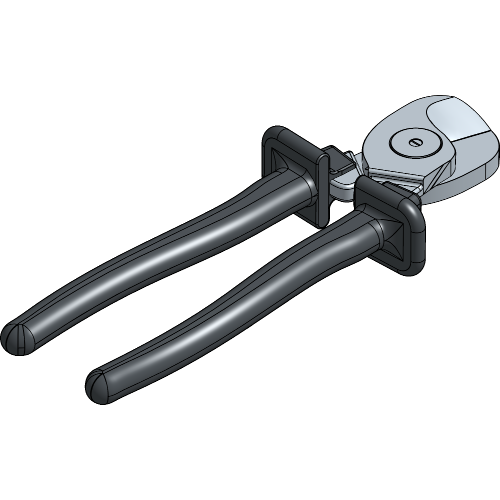
Throughout the manual, all bolts will need to be tightened with a wrench 13. It is most convenient to have two wrenches 13 or one wrench 13 and a power tool, as there will be one needed to hold the nut, and one needed to screw the bolt.
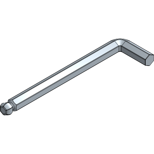
The allen key 3 will only be needed for the screws on the Wall Bracket Plates, Truss Clamp Plates or Suspension Plates if those are included in your setup.
ScreenFrame without Support Profiles
Place all Pieces of the frame on the floor with the front side facing down for easier assembly of your ScreenFrame.

The layout of all pieces can vary depending on your setup.
ScreenFrame with Support Profiles
Place all Pieces of the frame on the floor with the front side facing down for easier assembly of your ScreenFrame.

The layout of all pieces can vary depending on your setup.
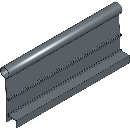
Slide a Base Profile on each side of the Outer Corner, with the front side facing down. Repeat this for each corner.
Define the suspension of your ScreenFrame and follow the associated steps.
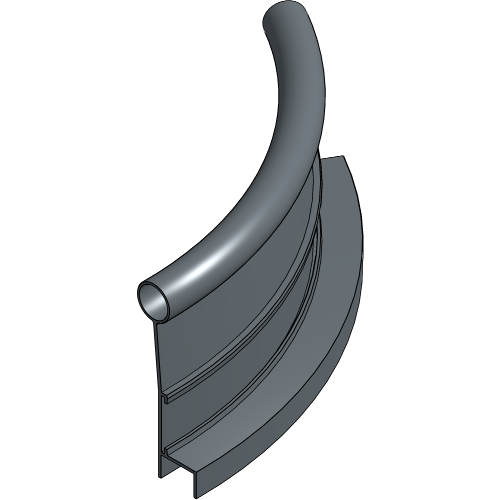
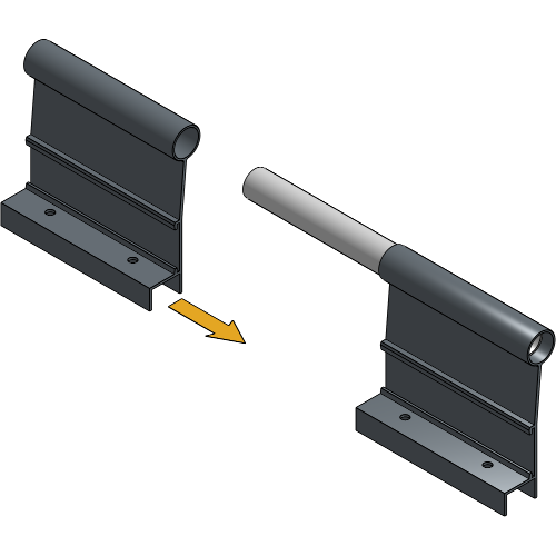
Place the Inner Corner into the Base Profile corner you just created in the previous step with the flat side to the front. Repeat this for each corner.
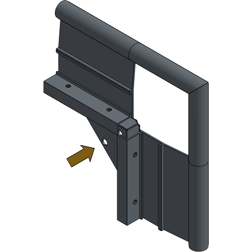
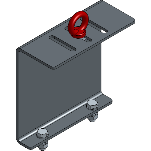
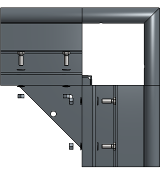
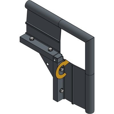
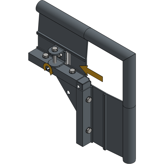
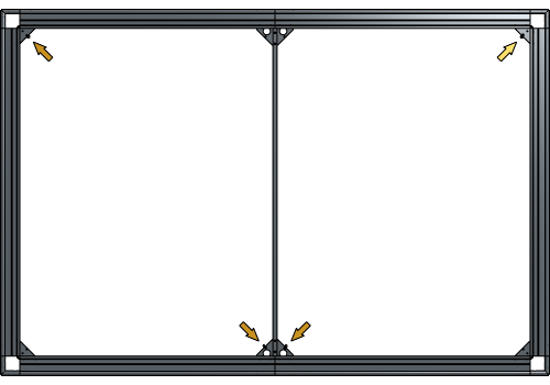
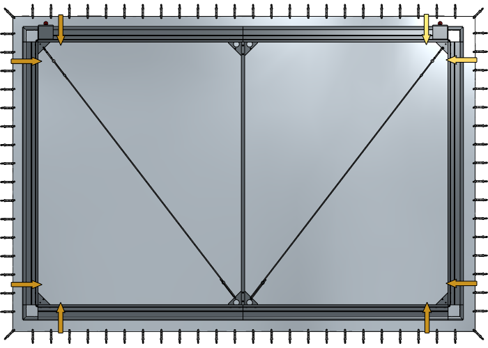
Place both Suspension sets with the flat side facing the back of
the screen on the 2 upper corners. 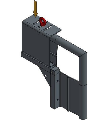
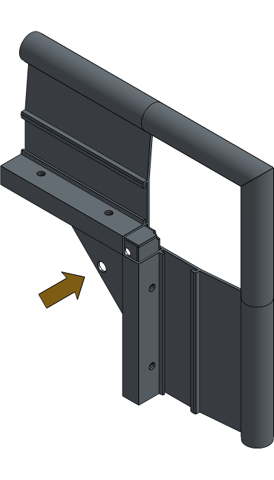
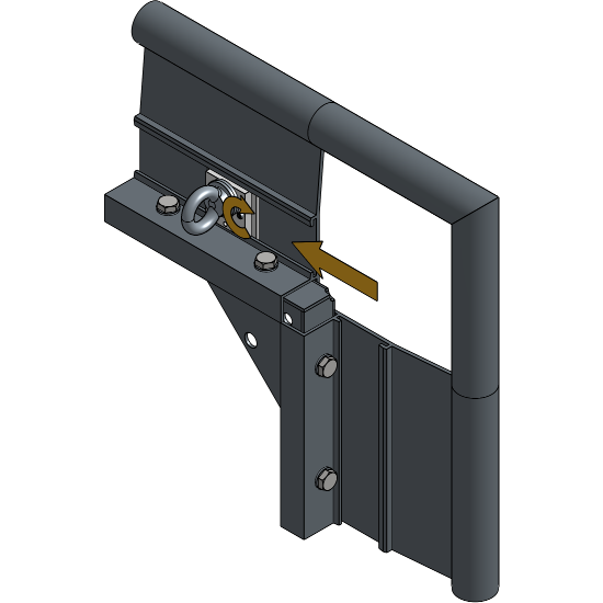
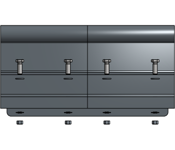
Secure the Suspension set, the Base Profile and the upper Inner Corner together with bolts.
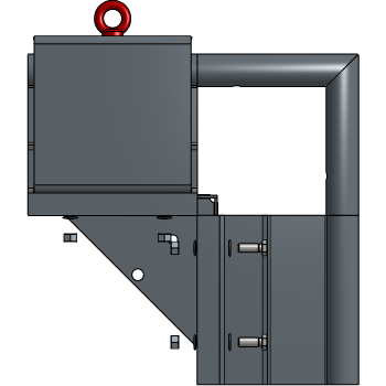
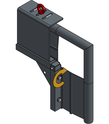
Secure the bottom Inner Corners to the Base Profile with bolts.
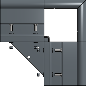
All steps from Suspension with a Suspension set are completed
For further installation steps, go to to Connecting the Base Profiles
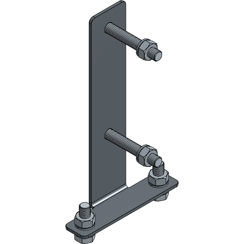
A ScreenFrame system suspended with Wall Bracket Plates should have one Wall Bracket Plate at every corner and every 3 to 4 m to distribute the load.
Place the Inner Corner into the Base Profile corner you just created in the previous step with the flat side to the front. Repeat this for each corner.
Secure all Inner Corners to the Base Profile with bolts.
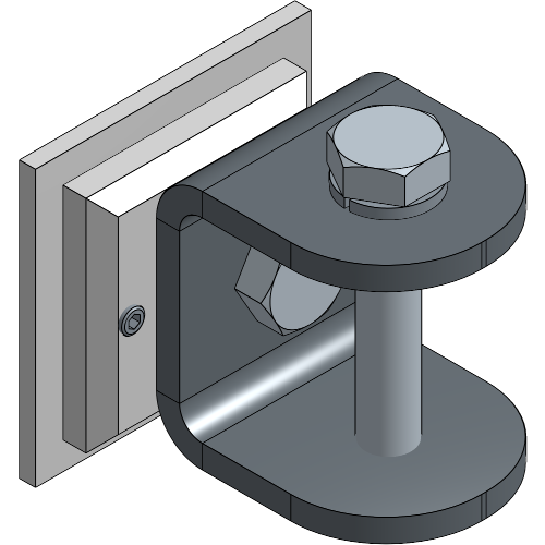
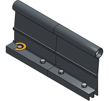
Slide the Wall Bracket Plate into the Base Profile and fasten the screws until they are locked in place.
All steps from Suspension with Wall Bracket Plates are completed
For further installation steps, go to to Connecting the Base Profiles
A ScreenFrame system suspended with Truss Clamp Plates should have one Truss Clamp Plate at every corner and all around every 1.5 m to distribute the load.
Place the Inner Corner into the Base Profile corner you just created in the previous step with the flat side to the front. Repeat this for each corner.
Secure all Inner Corners to the Base Profile with bolts.
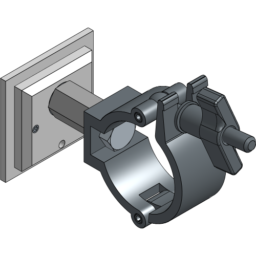
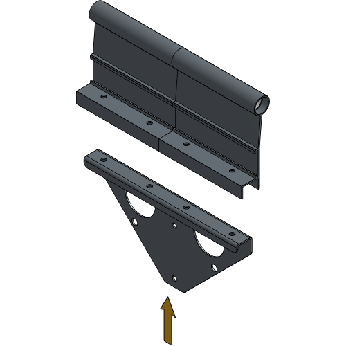
Slide the Truss Clamp Plate Plate into the Base Profile and fasten the screws until they are locked in place.

All steps from Suspension with Truss Clamp Plates are completed
For further installation steps, go to to Connecting the Base Profiles
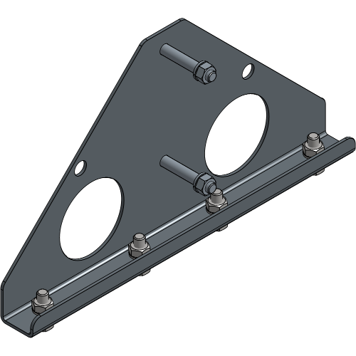
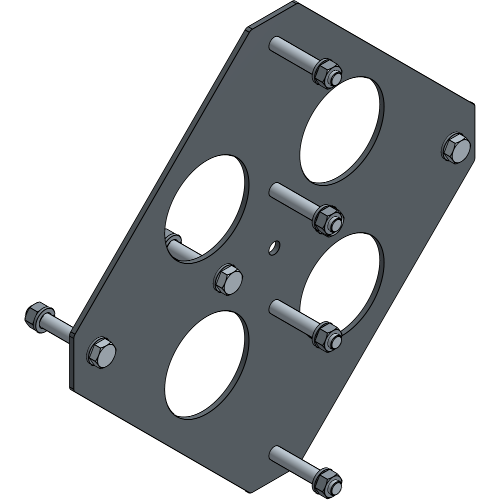
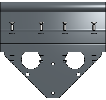
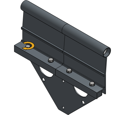
A ScreenFrame system suspended with Suspension Plates should have one Suspension Plate every 2 to 3 m to distribute the load.
Place the Inner Corner into the Base Profile corner you just created in the previous step with the flat side to the front. Repeat this for each corner.
Secure all Inner Corners to the Base Profile with bolts.
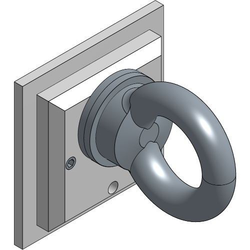
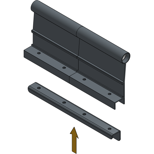
Slide the Suspension Plate into the Base Profile and fasten the screws until they are locked in place.
All steps from Suspension with Suspension Plates are completed
For further installation steps, go to to Connecting the Base Profiles
These steps are meant for frames that exist out of more than one Base Profile on each side. If your ScreenFrame only contains 4 Base Profiles and no Support Profiles, go to Positioning the Fabric.
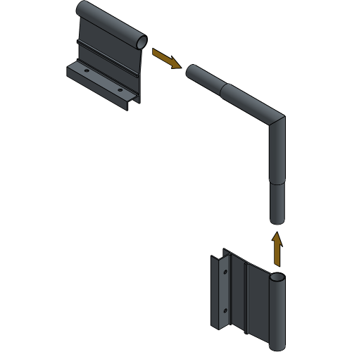
Slide the Base Profiles with the riveted Joint Pivot into the Base Profiles without the Joint Pivot.
Place the Joint Profiles with the long end directed to the front of the frame into the Base Profiles.
Secure the Joint Profiles to the Base Profiles with the bolts directed inwards.
These steps are meant for frames that exist out of more than one Base Profile at each side, larger than 6 m wide with a Support. If your ScreenFrame only contains Joint sets and no Joint Plates, go to Positioning the Fabric.
Slide the Base Profiles with the riveted Joint Pivot into the Base Profiles without the Joint Pivot.
Place the Joint Plates with the triangle directed to the front of the frame into the Base Profiles.
Secure the Joint Plates to the Base Profiles with bolts.
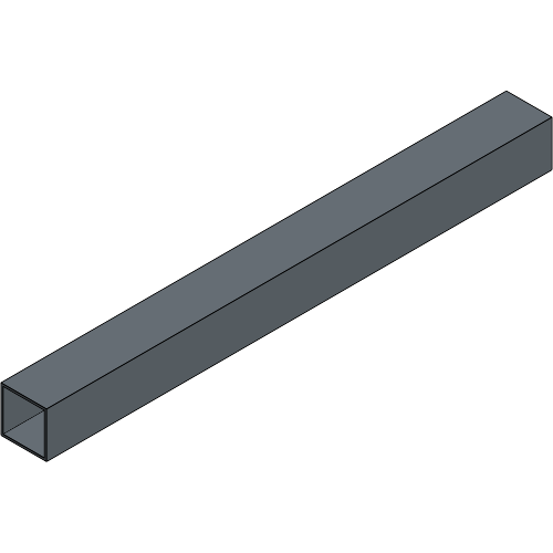
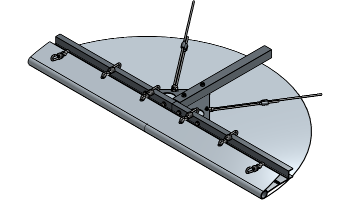
This depends on your ScreenFrame set-up, but make sure the distribution of the Support Profiles is correct. There should be 1 Support Profile placed every 3 m. It’s also possible to have a Support Profile in the middle of a Base Profile. If you don’t have vertical Supports included in your set-up, go to Positioning the Fabric.
Place the Support Profile across the frame on top of the Joint Plates.
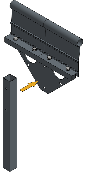
Secure the Support Profile to the Joint Profile with bolts and do this for all necessary Support Profiles.

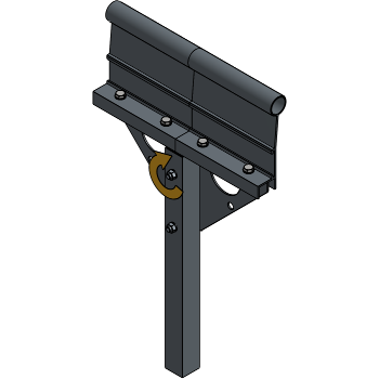
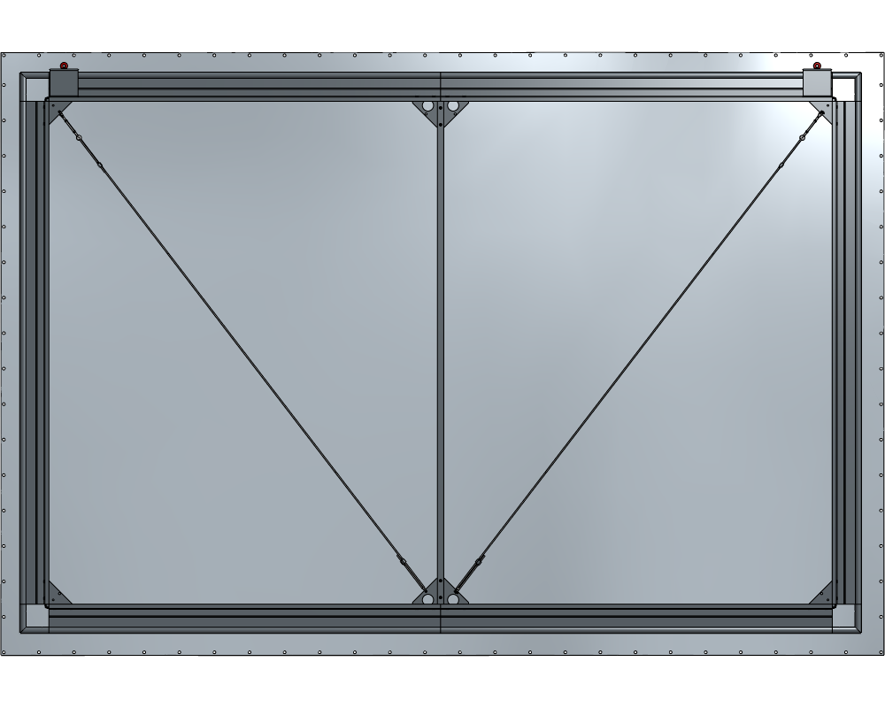
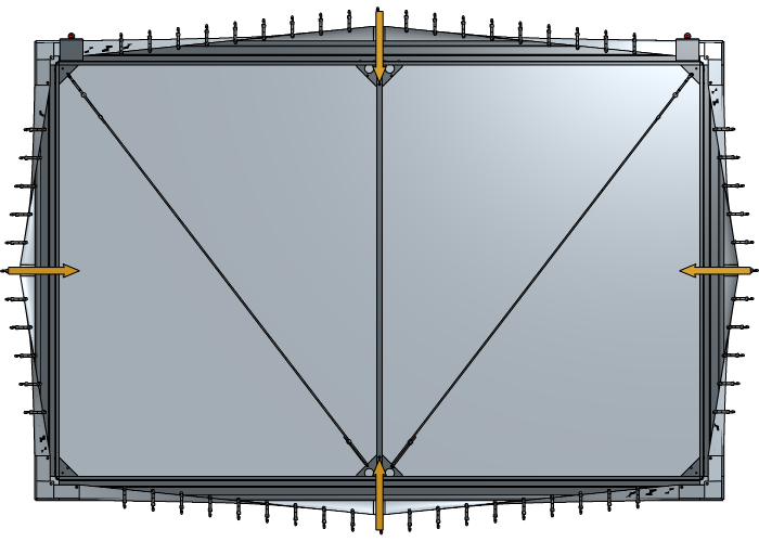
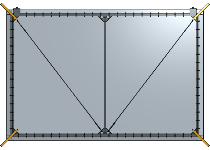
Tension sets are mostly used in combination with vertical supports in frames larger than 6 m wide and are only suspended in the inner corners. If you don’t have vertical supports and Tension sets included in your set-up, go to Positioning the Fabric.
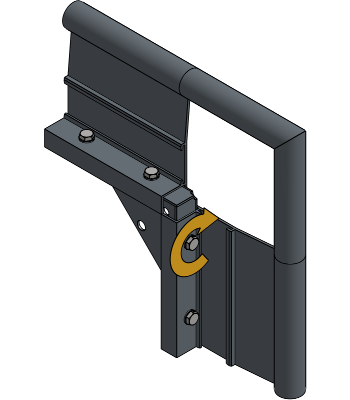
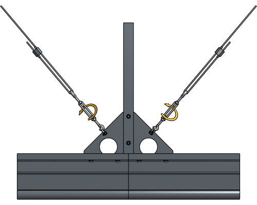
Place a D-Shackle into the hole of the upper Inner Corner and the hole of the closest opposite bottom Joint Plate.

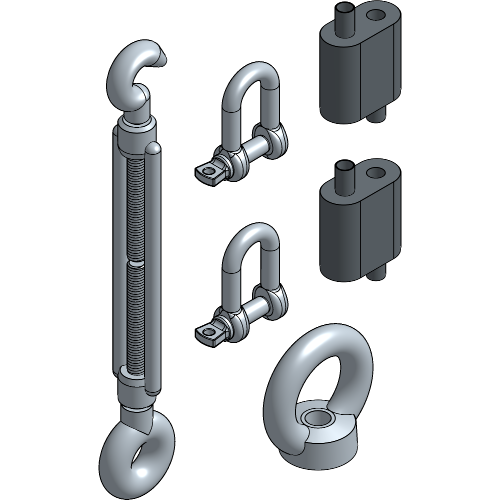
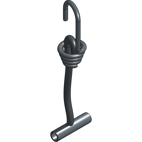
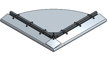
Loosen the Cable Spanner before assembling the rest of the Tension set by unscrewing the hook.

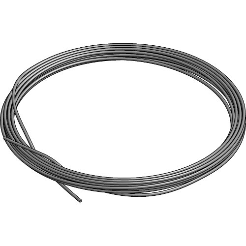
Insert the Steel Cable into one side of the Quick Suspension, thread it through the D-Shackle in the top corner, and back into the other side of the Quick Suspension. Do this for both parts of the frame.
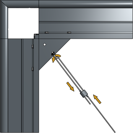
Insert the other end of the Steel Cable into one side of the other Quick Suspension, thread it through the Cable Spanner, and back into the other side of the Quick Suspension.
Hang the hook of the Cable Spanner on the D-Shackle of the Joint Plate. Do this for both parts of the frame.
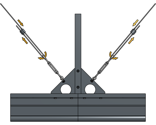
Adjust the cable length at the level of the Quick Suspensions until the cable can’t be pulled any further.
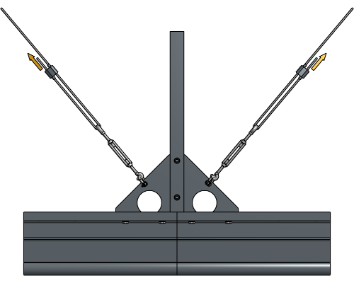
Add some more tension to the Steel Cable by screwing the Cable Spanner further until the bottom side of the frame is straight.
If you have two or more vertical Support Profiles, there should be two Tension sets in the middle section. Apply the same steps that are shown in this chapter.
Tension sets suspended on a Joint Plate in middle sections always use D-Shackles at both suspension points.


Roll out or unfold the fabric front side facing the floor and position your frame as correct as possible on top.
Make sure you have clean flooring and add protection foil.
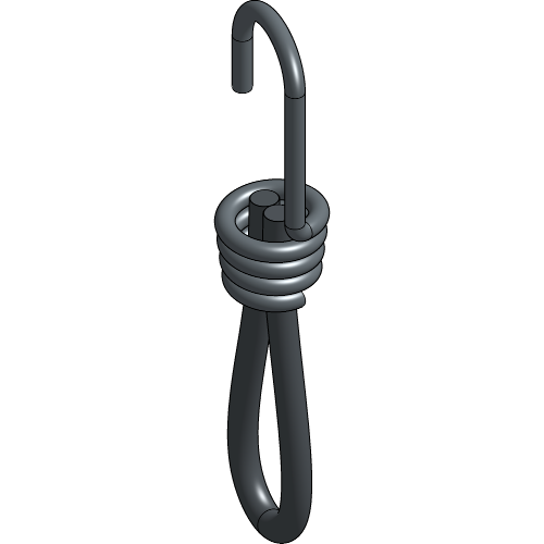
Pull a Spanfix Spiral Hook loop through each eye-lit of the fabric and thread the hook through its loop to secure it.
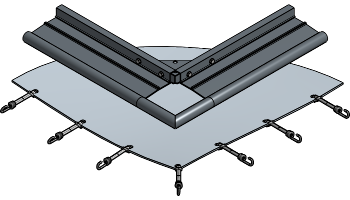
If you have a Spanfix Hook T, there is no loop. The hook gets pulled through the eye-lit of the fabric and is attached to the Base Profile as shown in the next steps. They are effortless to assemble and disassemble so they are mostly used for non-permanent installations.
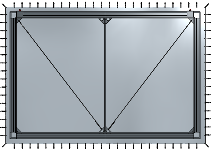
Lock the Spanfix hooks next to each corner onto the profile.

Lock the Spanfix hooks of each middle section onto the profile and continue to follow a middle-middle locking pattern to lock all sides.
The bigger your fabric is, the more important it will be to add the right tension and follow the “middle-middle” order.
Fold the corner until it’s nicely tucked away and lock the Spanfix hooks of all 4 corners onto the profile.
Avoid excessive tension on the fabric in the corners. If the fabric doesn’t fit when applying normal tension, use a longer Spanfix hook.
Your 0° Corner ScreenFrame is now completely assembled and ready to use!
For more technical assistance, please contact your local ShowTex
office.
The address and contact information can be found on our website:
www.showtex.com