Double PrintFrame
General
Installation manual

Installation manual
No part of this publication may be duplicated or edited in any form or by any means, including any type of electronic or mechanical method without prior written permission from ShowTex.
ShowTex and its employees are fully aware of their task to provide a reliable edition of this document. Nevertheless, they cannot accept any form of liability for the direct or indirect consequences of imperfections that might remain in this edition. The material in this manual is subject to change without notice.
ShowTex warrants that its mechanical and technical products, when delivered in new condition, in original packing, sold directly and used in normal conditions are free from any defects in manufacturing, materials and workmanship. For more information about your local warranty terms, please check our website or contact your local ShowTex office.
All products from the ShowTex Rental range are supposed to be returned in the same state as they were rented. Please treat our products with care, allowing the next user to enjoy the products as much as you did. The rented products are internally checked according to the general rental conditions. Be sure to check our rental guidelines on our website before installing and using this product: ShowTex rental guidelines
Read and understand this user manual before installing and or operating the system. Failure to follow the instructions in this document could result in serious injury!
Following the guidelines of this manual will reduce the risk of damaging the equipment or injuring yourself and the people around you. Nevertheless, ShowTex cannot be held accountable for any use or misuse of the equipment and supplies.
Damage to the system caused by any other method of installation than the one shown in this manual can only be repaired or fixed at the customer’s expense.
As a result of the above warning, any ShowTex product must be installed and operated by a qualified technician who knows its capabilities as well as its limitations.
In case you are uncertain about the eligibility of any hardware in your product, please get in touch with your local ShowTex office to receive additional guidance.
Thank you for choosing for ShowTex and purchasing one of our products. We want to ensure that your experience is as smooth and safe as possible, so we kindly request that you take a few moments to carefully read this manual before installing your new system.
This manual contains important information that will help you comply with health and safety regulations, as well as provide guidance on how to safely install, operate and maintain your product. Our team has taken great care to ensure that this manual is easy to understand and follow, using straightforward language and clear illustrations.
If you have any questions or concerns regarding the installation or use of your product, please feel free to contact your local ShowTex office. Our knowledgeable team members are always available to assist you and answer any questions you may have.
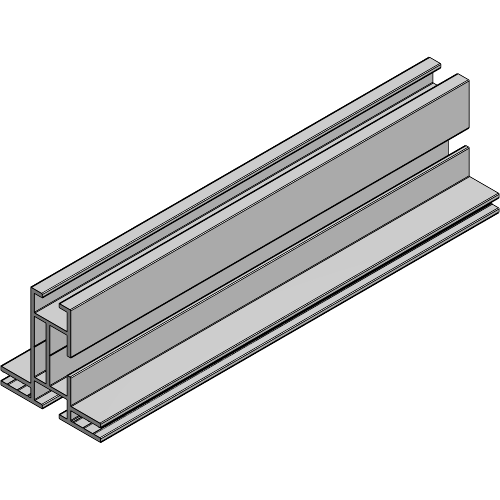
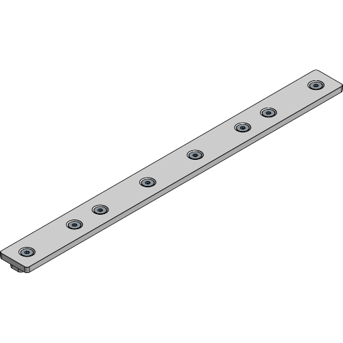
| Article number | Weight | Dimensions | Length | Colour |
|---|---|---|---|---|
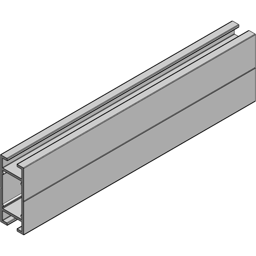
| 8840 0010 0024 | 0.89 kg/m | 49 x 46 mm | 6.00 m | Alu |
| 8840 0010 0217 | 0.89 kg/m | 50 x 50 mm | 6.00 m | Black |
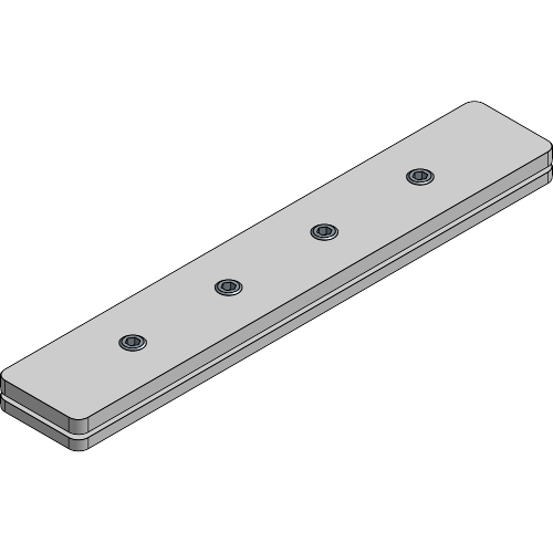
| Article number | Weight | Colour |
|---|---|---|
| 8840 4099 0004 | 0.20 kg | Alu |
| 8840 4099 0007 | 0.20 kg | Black |
| Article number | Weight | Colour |
|---|---|---|
| 8840 4099 0034 | 1.16 kg | Alu |
| 8840 4099 0037 | 1.16 kg | Black |
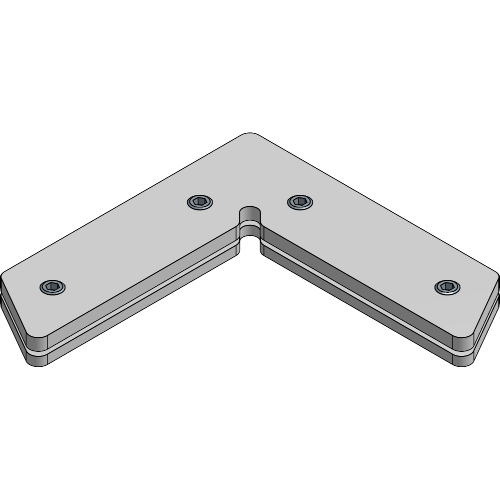
| Article number | Weight | Colour |
|---|---|---|
| 8840 0042 0004 | 0.21 kg | Alu |
| 8840 0042 0007 | 0.21 kg | Black |
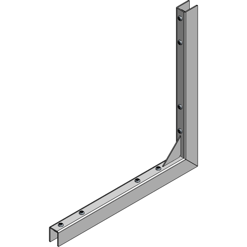
| Article number | Weight | Colour |
|---|---|---|
| 8840 4099 0044 | 0.75 kg | Alu |
| 8840 4099 0047 | 0.75 kg | Black |
| Article number | Weight | Colour |
|---|---|---|
| 8840 0042 0044 | 0.75 kg | Alu |
| 8840 0042 0047 | 0.75 kg | Black |
| Article number | Colour |
|---|---|
| 8185 4107 0200 | Grey |
| 8185 4107 0400 | Grey |
| Article number | Weight | Length | WLL | SF | ⌀ | Colour |
|---|---|---|---|---|---|---|
| 8840 9600 7121 | 0.05 kg | 2.50 m | 45.00 kg | 5:1 | 1.5 mm | Alu |
| 8840 9600 7127 | 0.05 kg | 2.50 m | 45.00 kg | 5:1 | 1.5 mm | Black |
| 8840 9600 7151 | 0.11 kg | 5.00 m | 45.00 kg | 5:1 | 1.5 mm | Alu |
| 8840 9600 7191 | 0.21 kg | 10.00 m | 45.00 kg | 5:1 | 1.5 mm | Alu |

| Article number | Weight | WLL | SF | ⌀ |
|---|---|---|---|---|
| 8840 9600 7101 | 0.02 kg/m | 45.00 kg | 5:1 | 1.5 mm |
| 8840 9600 7231 | 0.04 kg/m | 90.00 kg | 5:1 | 3.0 mm |
| Article number | Weight | WLL | SF | Colour |
|---|---|---|---|---|
| 8840 9600 1564 | 0.01 kg | 45.00 kg | 5:1 | Alu |
| Article number | Weight | WLL | SF | Colour |
|---|---|---|---|---|
| 8840 9600 3064 | 0.06 kg | 60.00 kg | 5:1 | Alu |
| 8840 9600 3067 | 0.06 kg | 60.00 kg | 5:1 | black |
| Article number | Weight | WLL | SF | ⌀ | Colour |
|---|---|---|---|---|---|
| 8700 0304 0414 | 0.01 kg | 45.00 kg | 5:1 | 1.5 mm | Alu |
| 8700 0304 0417 | 0.01 kg | 45.00 kg | 5:1 | 1.5 mm | Black |
| Article number | Weight | WLL | SF | ⌀ | Colour |
|---|---|---|---|---|---|
| 8700 0304 0424 | 0.03 kg | 90.00 kg | 5:1 | 3.0 mm | Alu |
| 8700 0304 0427 | 0.03 kg | 90.00 kg | 5:1 | 3.0 mm | Black |
| Article number | Weight | Colour |
|---|---|---|
| 8840 2000 0004 | 1.73 kg | Alu |
| 8840 2000 0007 | 1.73 kg | Black |
| Article number | Weight | Dimensions | Length | Colour |
|---|---|---|---|---|
| 8840 0010 0224 | 0.68 kg | 16.5 x 50 mm | 6.00 m | Alu |
| 8840 0010 0227 | 0.68 kg | 16.5 x 50 mm | 6.00 m | Black |
| Article number | Weight | Colour |
|---|---|---|
| 8840 0010 0044 | 0.05 kg | Alu |
| 8840 0010 0047 | 0.05 kg | Black |
| Article number | Weight | Colour |
|---|---|---|
| 8840 0010 0334 | 0.04 kg | Alu |
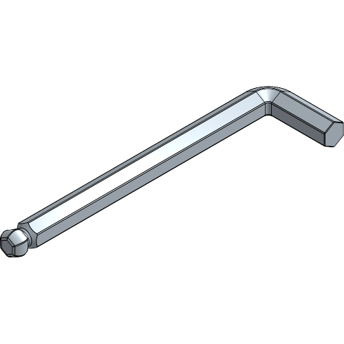
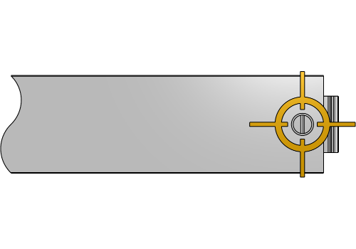
Throughout the manual, all set screws will be tightened with an allen key 3, the allen key 5 will only be needed to install Brace Profiles.
Take precaution when working with cut aluminium profiles such as the Double PrintFrame. Cut edges are sharp and should be handled carefully not to harm yourself or damage flooring.
When assembling the Frame, check for cutouts on the edges of the profile. Cutouts are provided for supsension, to insert a Base Plate or connect profiles. Make sure all cutouts are placed at the top and/or bottom to be able to insert all equipment later on.
When no cutouts are provided, all equipment should be inserted into the profiles upfront before assembling. Consult the chapters Standing PrintFrame and Suspended PrintFrame for the display steps, and check Connecting Frames in-Line and Connecting Frames in a Corner for frame connection steps.
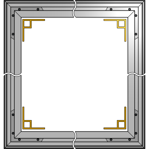
PrintFrame without Brace Profiles
Lay all Pieces of the frame on the floor with the front side facing up for easier assembly of your PrintFrame.
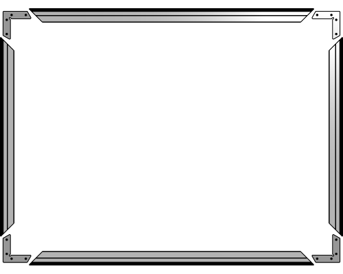
The arrangement of all pieces may vary depending on your setup.
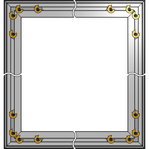
PrintFrame with Brace Profiles
Lay all Pieces of the frame on the floor with the front side facing up for easier assembly of your PrintFrame.
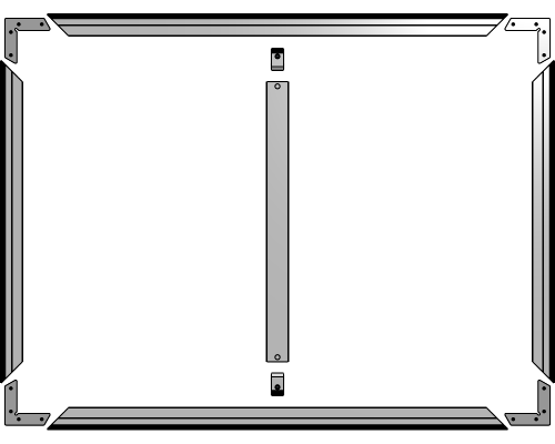
The arrangement of all pieces may vary depending on your setup.
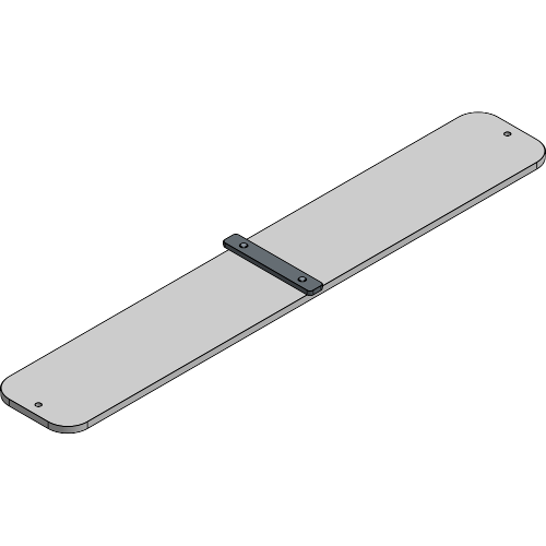
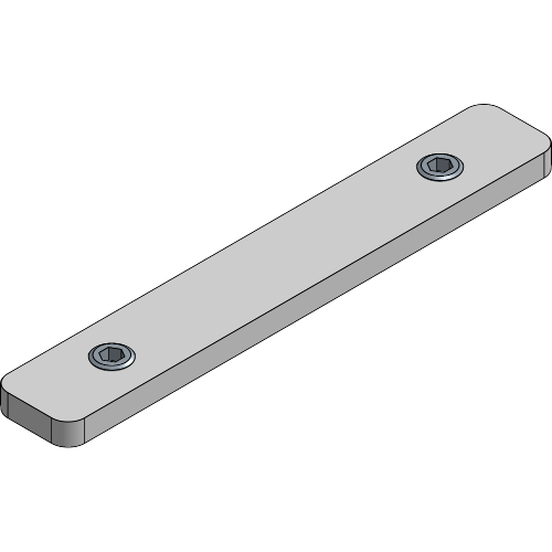
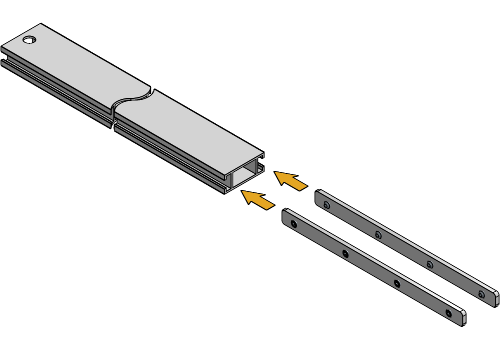
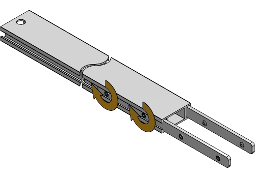
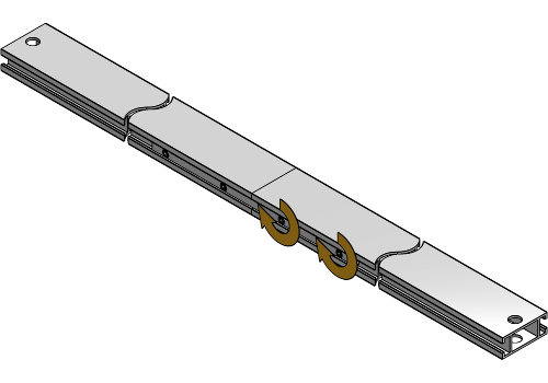
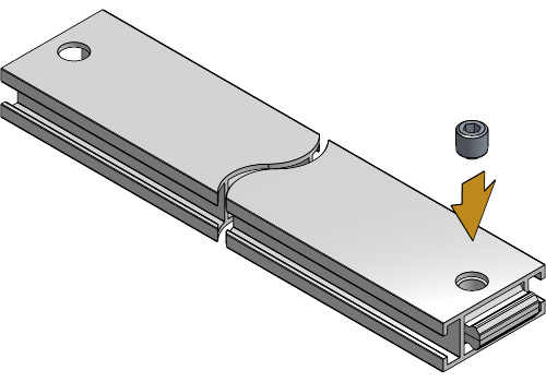
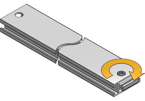
If your frame consists of sections that require lengthwise connection, insert the Joint Plate halfway into the first profile and slightly tighten the first two set screws.
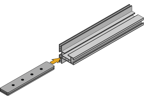
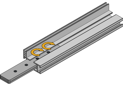
Slide the second profile over the other half of the Joint Plate, make sure the keder slots are aligned, then tighten all set screws. Repeat this for all Joint Plate connections.
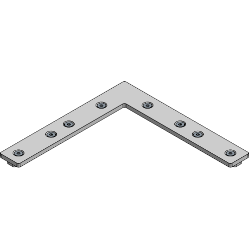
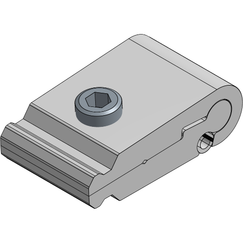
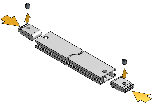
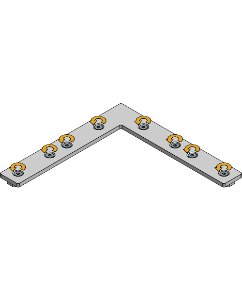
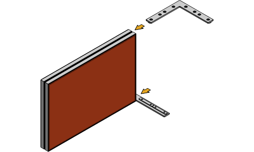
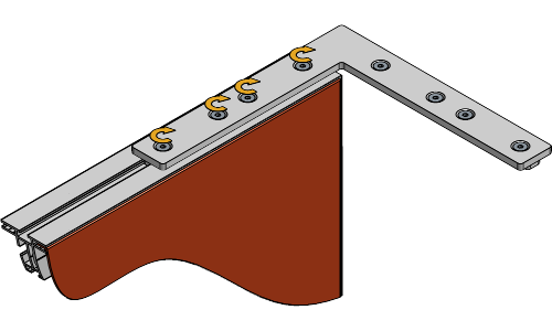
Insert two Corner Connection sets into the first side of the frame.
Slide two other profiles over the Corner Connection sets, adjust the corners to a clean 90° angle and slightly tighten the set screws.
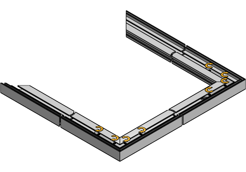
Insert two Corner Connection sets into the last side of the frame.
Insert the last profile into the U-shape you assembled in the previous steps to complete the frame.
Adjust until all corners to a clean 90° angle and align all keder slots.
Tighten all set screws of the Corner Connection sets.
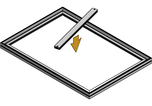
The following steps only apply to Double PrintFrame setups with Brace Profiles. If your setup does not include Brace Profiles, proceed to the chapter Inserting the Fabric.
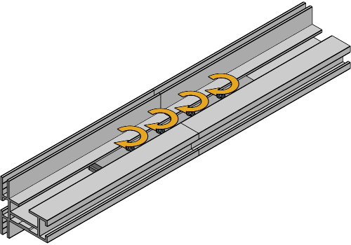
If your Profile exceeds 6 m in length, the Brace Profile will have to be extended. Insert the Brace Joint Plates into the first Brace Profile and slightly tighten the set screws.
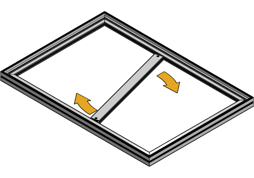
Slide the second Brace Profile over the Brace Joint Plates and tighten all set screws to fully secure the Brace Profiles together.
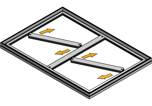
Insert the Brace Lock with the rounded side into both sides of the Brace Profile and align the hole of the Brace Profile and socket of the Brace Lock.
Insert the set screw and tighten it until right before the Brace Lock starts to open up.
Insert the vertical Brace Profile into the Frame and position them in a 90° angle on the PrintFrame Profile.
Tighten the set screws on both sides of the Brace Profile.
If there are horizontal Brace Profiles included, insert one end into the side of the frame and one end into the vertical Brace Profile, then tighten the set screws hand-tight.
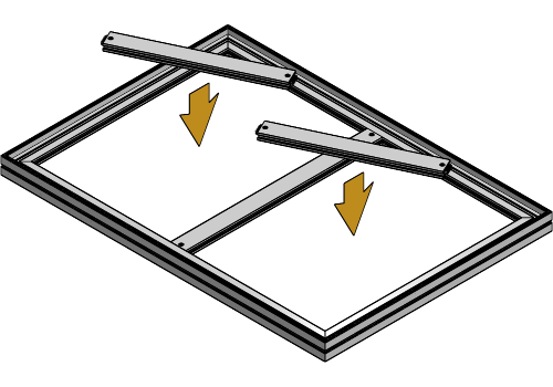
Tighten the set screws on both ends of the Brace Profiles.
The amount and the distance for Brace Profiles will depend on your Double PrintFrame setup, but the distance between profiles should never exceed 2.20 m.
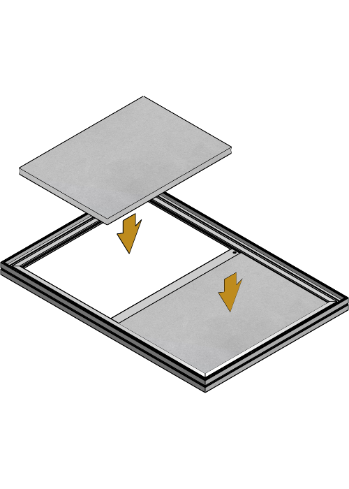
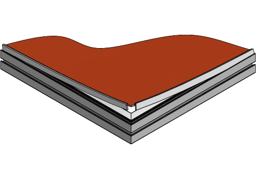
If your setup includes Acoustic Foam, insert it into the frame before you start inserting the fabric keder.
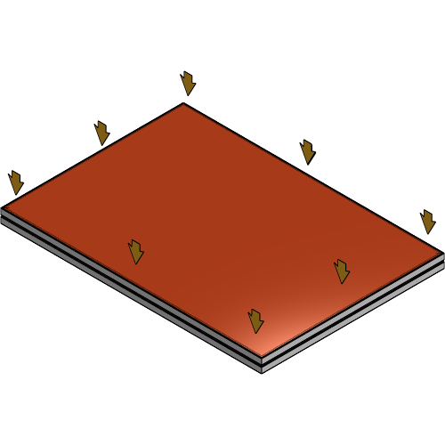
To align your fabric with the frame, insert the keder into the keder slot without the fabric on all sides of the frame.
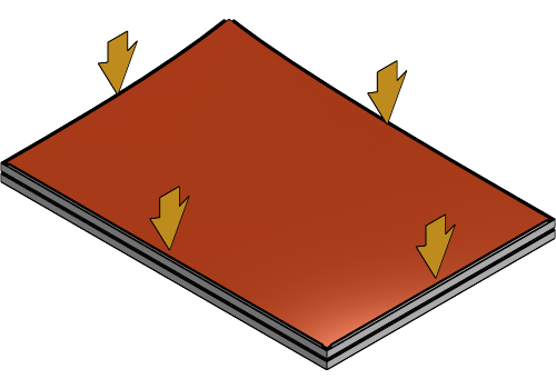
Begin at the longest side of the frame and fold the fabric over the keder. As you work towards the corners, periodically insert the keder into the slot.


At the corners, fold the excess fabric inward and insert the keder into the frame corners. Repeat this for both corners of the longest side.
Repeat these steps for the opposite side of the frame.
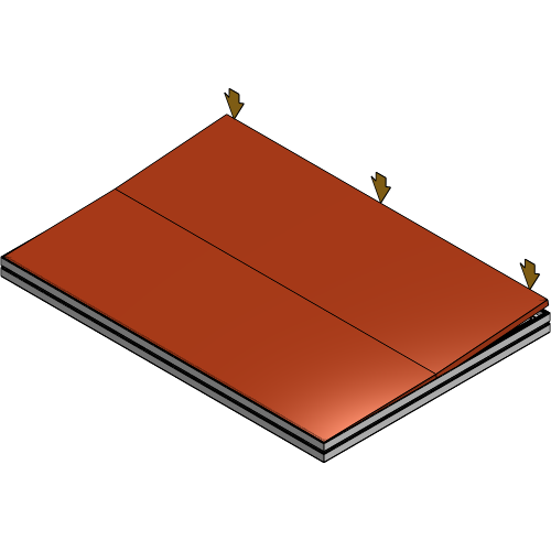
Fold the fabric over the keder insert the remaining two sides into the keder slot.
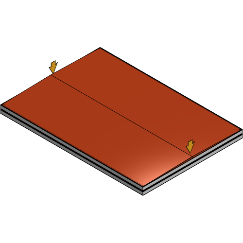
Push any remaining bumps along the profile further into the keder slot to fully secure the fabric.
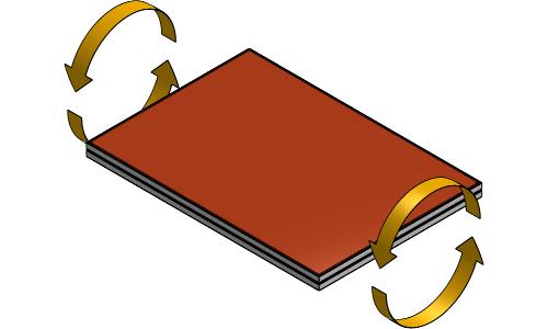
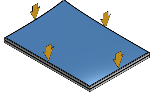
Flip the frame and repeat the previous steps to insert the fabric on the other side of the frame.
Define the to display your Double PrintFrame and follow the associated steps.
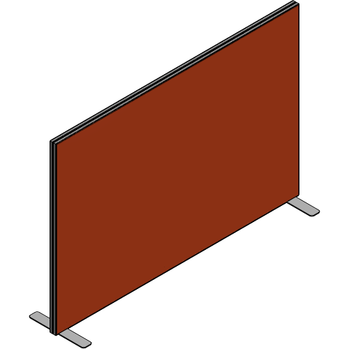
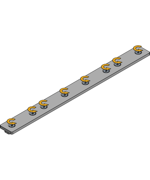
Inserting the equipment for a standing PrintFrame when the frame has been assembled is only possible if slots are provided to slide the Joint Plates into the frame.
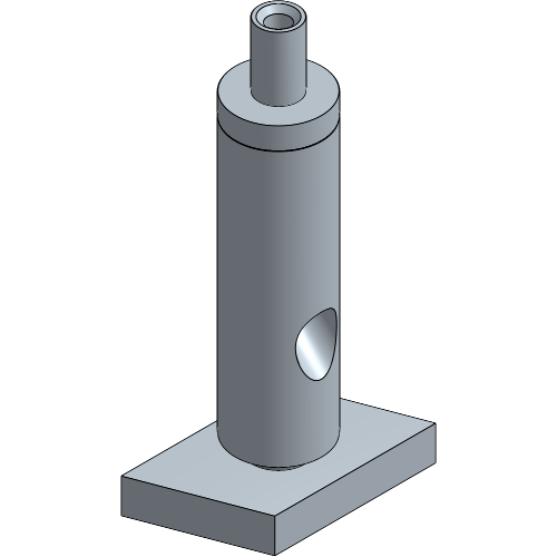
Loosen the set screws of the Base Plate until the Joint Plate has enough space to slide into the PrintFrame Profile.
Insert the Base Plate with the Joint Plate into the bottom of the PrintFrame Profile.
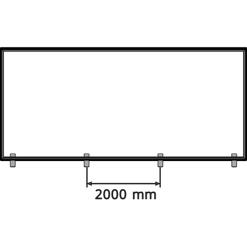
Repeat until you have at least one Base Plate every 2 m.
Tighten the set screws of the Base Plate to secure it to the PrintFrame Profile.
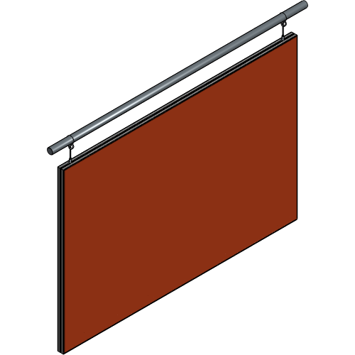
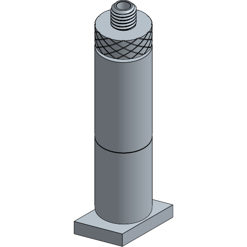
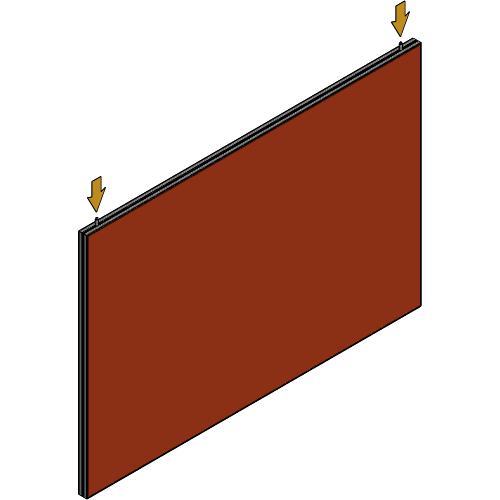
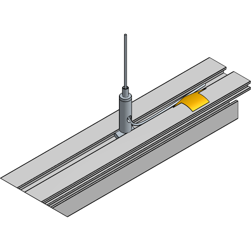
Inserting the equipment for a suspended PrintFrame when the frame has been assembled is only possible if slots are provided to slide the channel nuts into the frame.
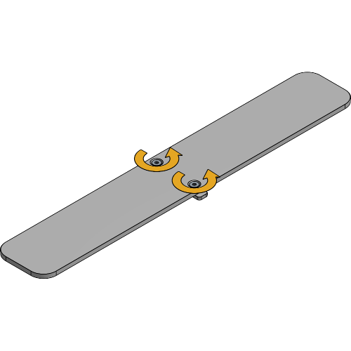
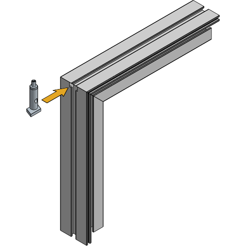
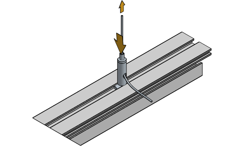
Loosen the channel nut of the Cable Holder until it has enough room to slide into the profile.
Slide the channel nut of the cable Holder into the top of the PrintFrame.
Position a Cable Holder at each corner of the PrintFrame.
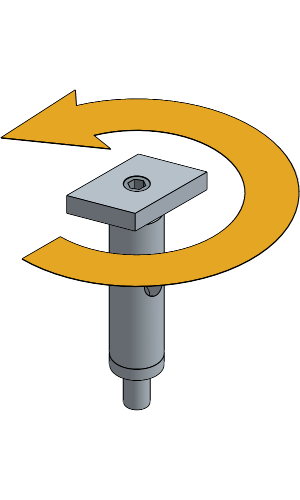
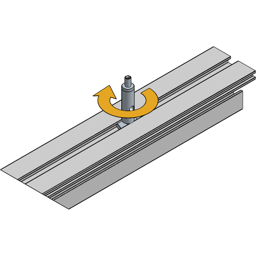
Tighten the set screws Channel nut by turning the Cable Holder.
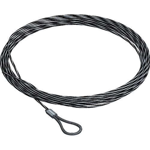
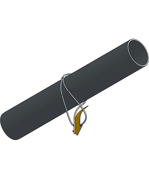
Hang the Steel Cable over your suspension choice and pull the end of the cable through the loop.
Pull the steel cable through the Cable holder. Adjust by pressing the nut down and pulling the cable back if necessary.
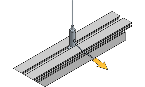
Hide the excess cable inside the Profile for a clean finish.
Define the to display your Double PrintFrame and follow the associated steps.
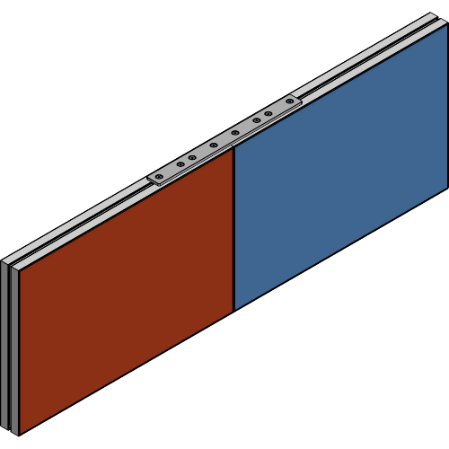
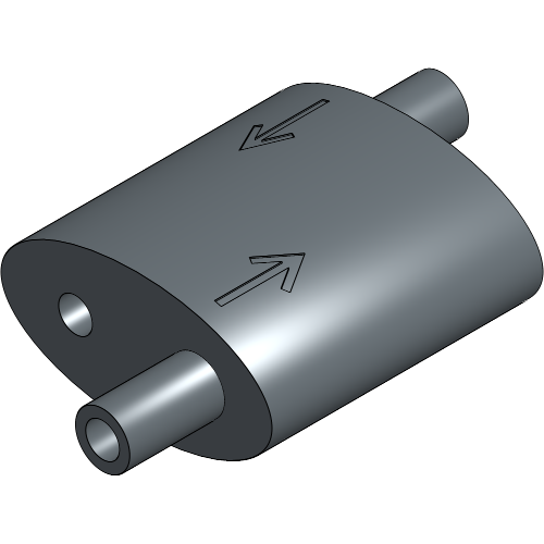
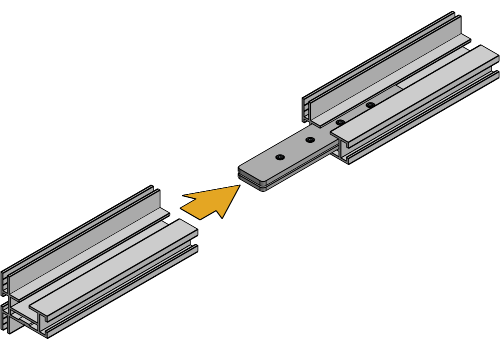
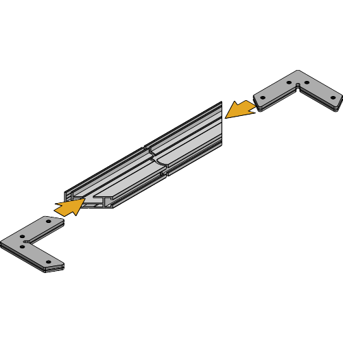
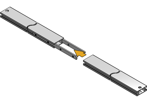
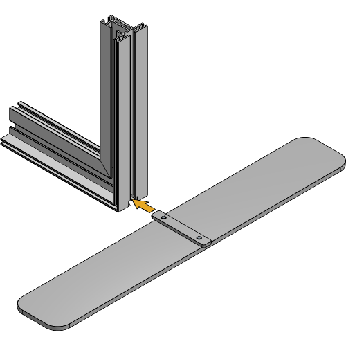
Inserting the equipment for an in-line connected PrintFrame is only possible if slots are provided to slide the Joint Plates into the frame.
Loosen the set screws of the Frame Joint Plate until the four Joint Plates have enough room to slide into the profile.
Slide the Frame Joint Plate halfway into the top and bottom of the first PrintFrame.
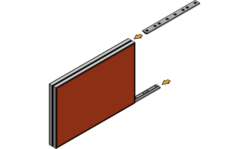
Slide the second PrintFrame over both Frame Joint Plates.
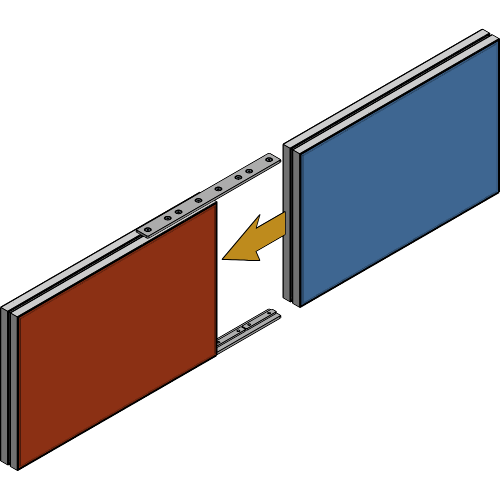
Align the Frame Joint Plate and tighten the set screws to secure it to the profile.

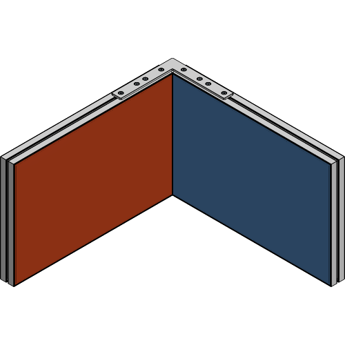
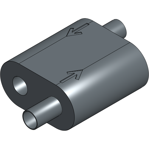
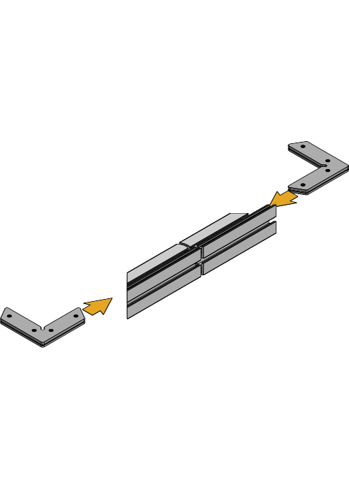
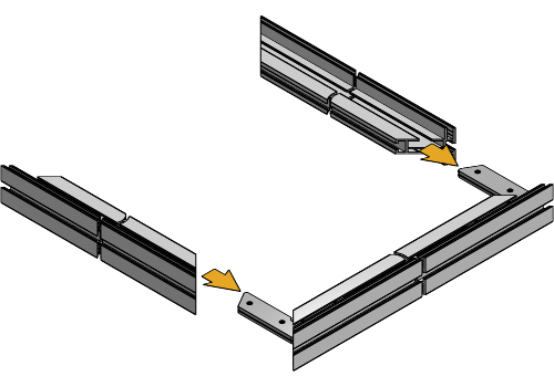
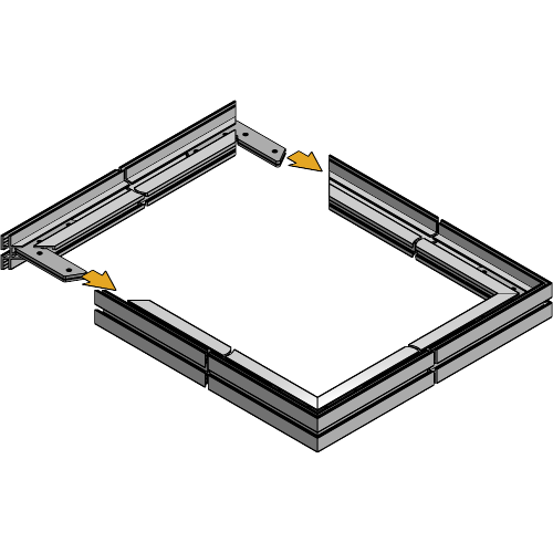
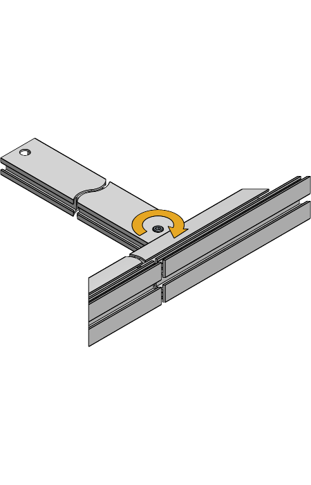
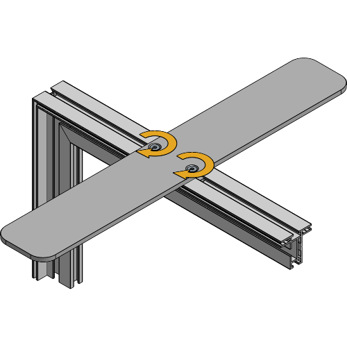
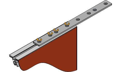
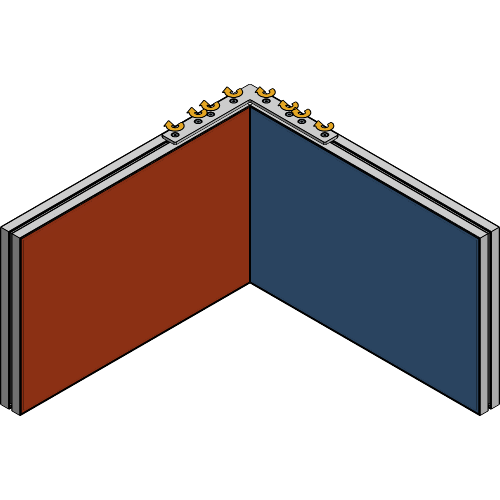
Inserting the equipment for a corner connected PrintFrame is only possible if slots are provided to slide the Joint Plates into the frame.
Loosen the set screws of the Frame Corner Connection set until the Joint Plates have enough room to slide into the profile.
Slide the Frame Corner Connection set halfway into the top and bottom of the first PrintFrame.
Slide the second PrintFrame over both Frame Corner Connection sets.
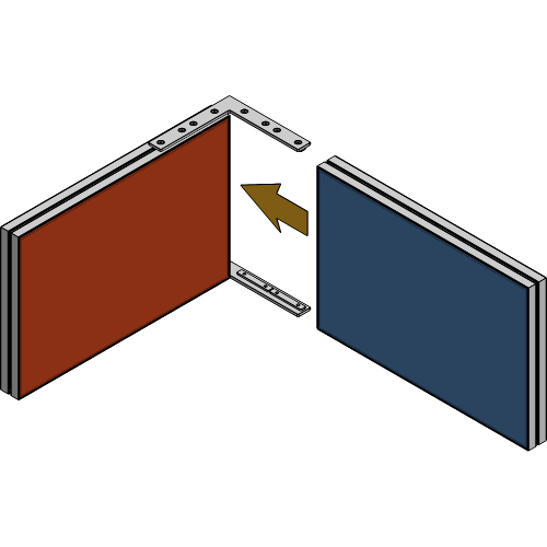
Align the Frame Corner Connection set and tighten the set screws to secure it to the profile.
Your Double PrintFrame is now fully assembled!
For more technical assistance, please contact your local ShowTex
office.
The address and contact information can be found on our website:
www.showtex.com