Cube PrintFrame
General
Installation manual

Installation manual
No part of this publication may be duplicated or edited in any form or by any means, including any type of electronic or mechanical method without prior written permission from ShowTex.
ShowTex and its employees are fully aware of their task to provide a reliable edition of this document. Nevertheless, they cannot accept any form of liability for the direct or indirect consequences of imperfections that might remain in this edition. The material in this manual is subject to change without notice.
ShowTex warrants that its mechanical and technical products, when delivered in new condition, in original packing, sold directly and used in normal conditions are free from any defects in manufacturing, materials and workmanship. For more information about your local warranty terms, please check our website or contact your local ShowTex office.
All products from the ShowTex Rental range are supposed to be returned in the same state as they were rented. Please treat our products with care, allowing the next user to enjoy the products as much as you did. The rented products are internally checked according to the general rental conditions. Be sure to check our rental guidelines on our website before installing and using this product: ShowTex rental guidelines
Read and understand this user manual before installing and or operating the system. Failure to follow the instructions in this document could result in serious injury!
Following the guidelines of this manual will reduce the risk of damaging the equipment or injuring yourself and the people around you. Nevertheless, ShowTex cannot be held accountable for any use or misuse of the equipment and supplies.
Damage to the system caused by any other method of installation than the one shown in this manual can only be repaired or fixed at the customer’s expense.
As a result of the above warning, any ShowTex product must be installed and operated by a qualified technician who knows its capabilities as well as its limitations.
In case you are uncertain about the eligibility of any hardware in your product, please get in touch with your local ShowTex office to receive additional guidance.
Thank you for choosing for ShowTex and purchasing one of our products. We want to ensure that your experience is as smooth and safe as possible, so we kindly request that you take a few moments to carefully read this manual before installing your new system.
This manual contains important information that will help you comply with health and safety regulations, as well as provide guidance on how to safely install, operate and maintain your product. Our team has taken great care to ensure that this manual is easy to understand and follow, using straightforward language and clear illustrations.
If you have any questions or concerns regarding the installation or use of your product, please feel free to contact your local ShowTex office. Our knowledgeable team members are always available to assist you and answer any questions you may have.
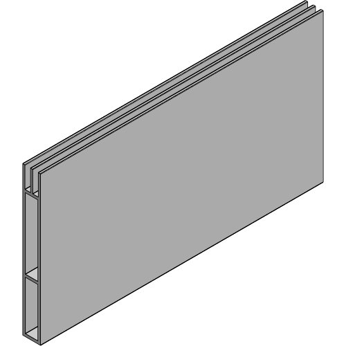
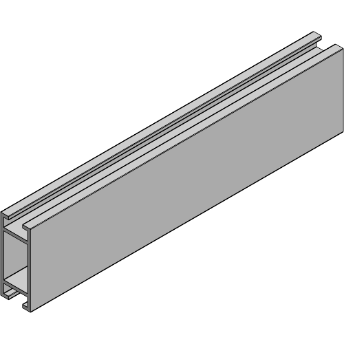
| Article number | Colour | Weight | Length |
|---|---|---|---|
| 8843 0010 0014 | Alu | 1.19 kg/m | 6.00 m |
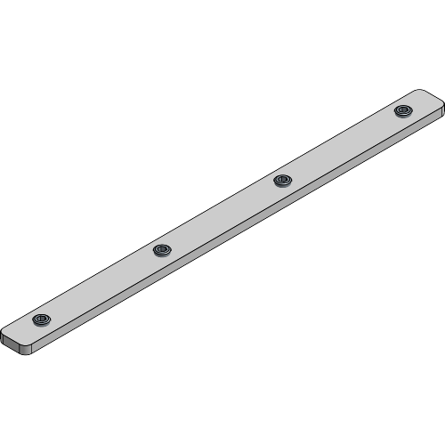
| Article number | Colour | Weight |
|---|---|---|
| 8843 0041 0014 | Alu | 0.05 kg |
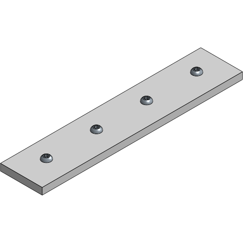
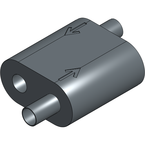
| Article number | Colour | Weight |
|---|---|---|
| 8843 4099 0014 | Alu | 0.25 kg |
| Article number | Colour | Weight |
|---|---|---|
| 8843 9600 0034 | Alu | 0.01 kg |
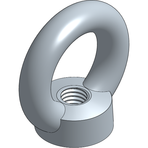
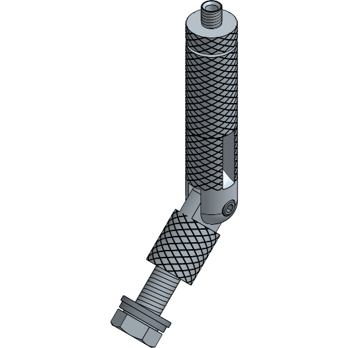
| Article number | Colour | Weight | WLL | SF |
|---|---|---|---|---|
| 8700 9221 0081 | Galvanised | 0.01 kg | 230.00 kg | 2:1 |
| Article number | Colour | Weight | ⌀ | WLL | SF |
|---|---|---|---|---|---|
| 8700 0304 0424 | Alu | 0.02 kg/m | 3.0 mm | 90.00 kg | 5:1 |
| 8700 0304 0427 | Black | 0.02 kg/m | 3.0 mm | 90.00 kg | 5:1 |

| Article number | Colour | ⌀ | WLL | SF |
|---|---|---|---|---|
| 8700 0304 0031 | Alu | 3.0 mm | 90.00 kg | 5:1 |
| 8700 0304 0007 | Black | 3.0 mm | 90.00 kg | 5:1 |
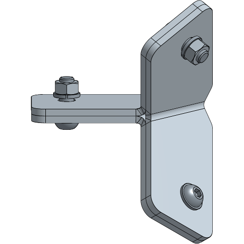
| Article number | Colour | Weight |
|---|---|---|
| 8840 0010 0034 | Alu | 0.68 kg |
| 8840 0010 0037 | Black | 0.68 kg |
| Article number | Colour | Weight |
|---|---|---|
| 8840 0042 0054 | Alu | 0.05 kg |
| 8840 0042 0057 | Black | 0.05 kg |
| Article number | Colour | Weight |
|---|---|---|
| 8843 0041 0004 | Alu | 0.04 kg |
| Article number | Colour | Weight |
|---|---|---|
| 8840 0010 0334 | Alu | 0.04 kg |

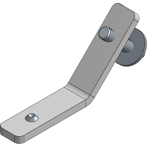
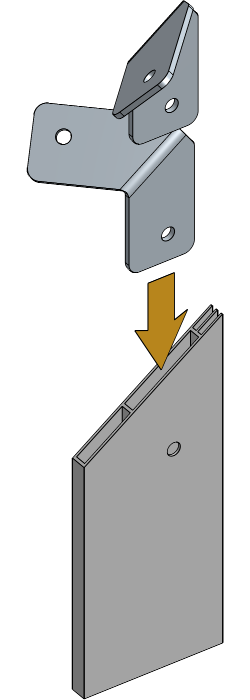
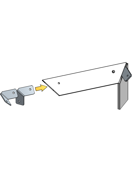
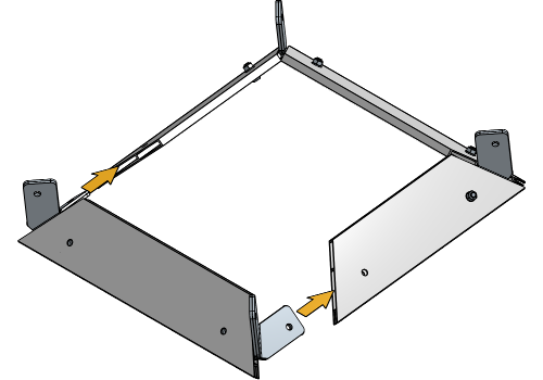
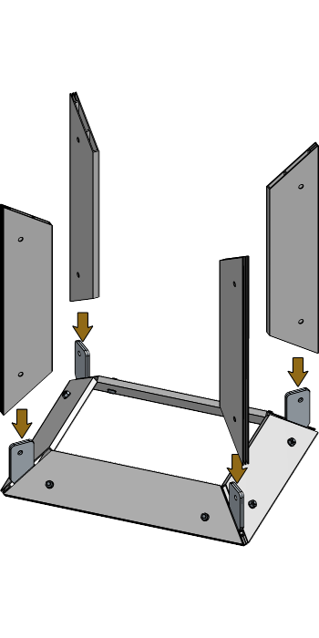
Insert two Corner Connection Plates into the first Cube Profile of the base.
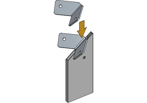
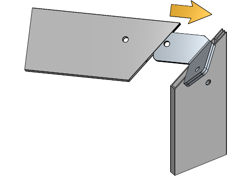
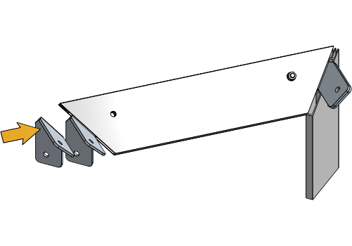
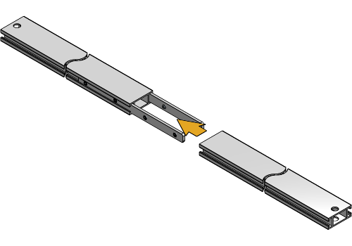
Add a third Corner Connection Plate to the corner and slide another Cube Profile over the Corner Connection Plates.
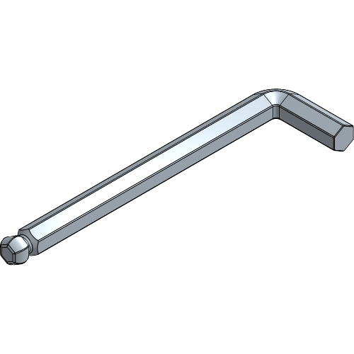
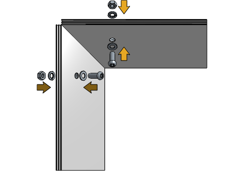
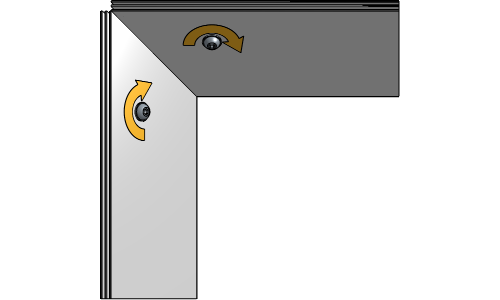
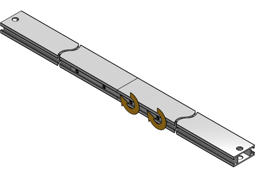
Insert the bolts with washers and spring washers into the Cube Profile, and tighten them slightly.
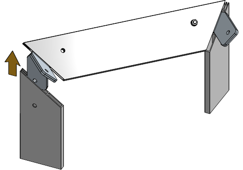
Insert two Corner Connection Plates into one of the ends of the assembled frame.
Add a third Corner Connection Plate to the corner and slide another Cube Profile over the Corner Connection Plates.
Insert the bolts with washers and spring washers into the Cube Profile and tighten them slightly.
Insert two Corner Connection Plates into the last Cube Profile of the base.
To insert the last profile into the assembled base, ensure that the corners are placed inside this profile, not the assembled base.
Add a third Corner Connection Plate to both corners and slide them into the Cube Profiles of the base.
Insert the bolts with washers and spring washers into the Cube Profile and tighten them slightly.
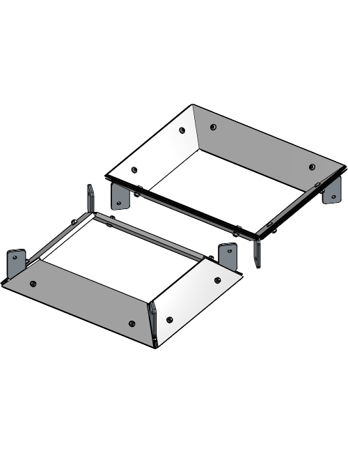
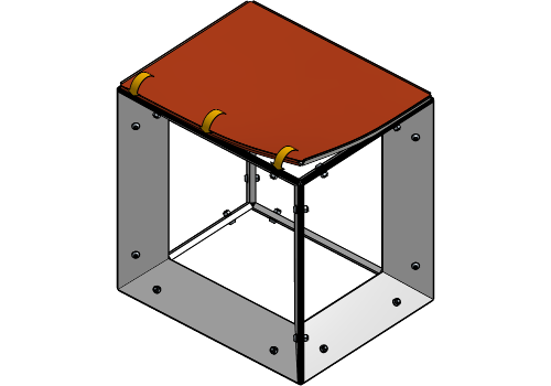
Repeat all previous steps to assemble the top of the Cube PrintFrame.
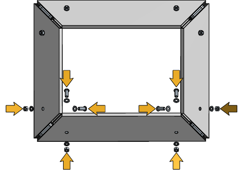
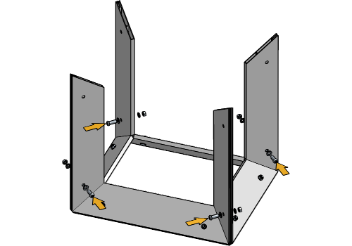
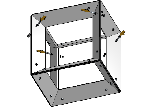
Insert the side Cube Profiles into the base you created in the previous steps.
Insert the bolts with washers and spring washers into the Cube Profile and tighten them slightly.
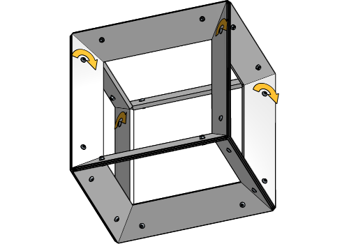
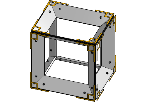
Insert the Corner Connection Plates of the top into the upper side of the side Cube Profiles.
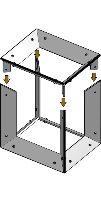
Insert the bolts with washers and spring washers into the Cube Profile and tighten them slightly.
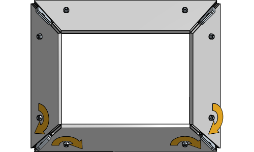
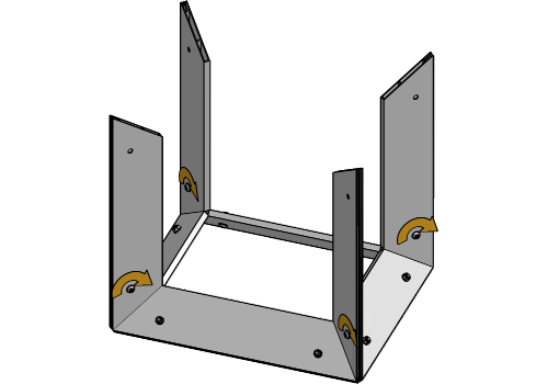
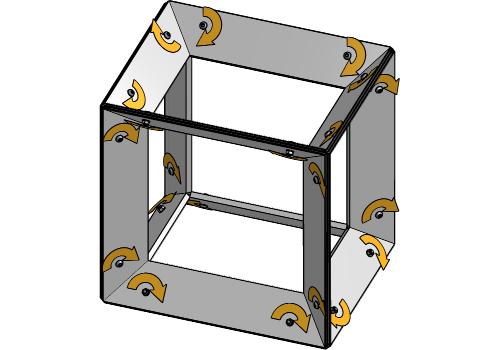
Align all corners with each other, and tighten all bolts.
The following steps only apply to Cube PrintFrame setups with Brace Profiles. If your setup does not include Brace Profiles, proceed to the chapter Inserting the Fabric.
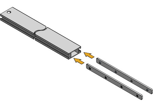
If your Profile exceeds 6 m in length, the Brace Profile will have to be extended. Insert the Brace Joint Plates into the first Brace Profile, and slightly tighten the set screws.
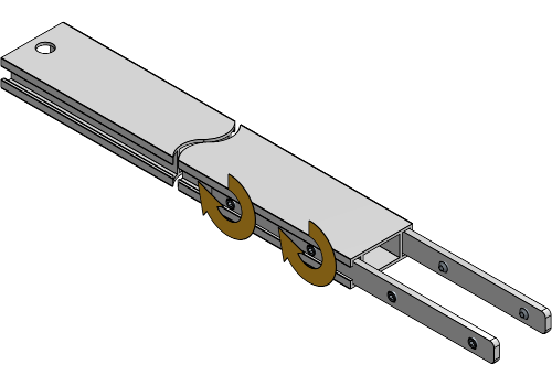
Slide the second Brace Profile over the Brace Joint Plates, and tighten all set screws to fully secure the Brace Profiles together.
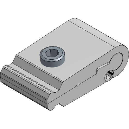
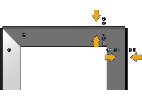
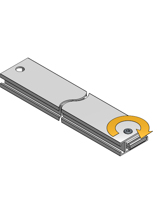
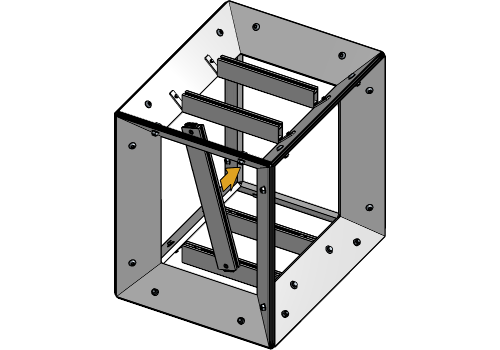
Insert the Brace Lock with the rounded side into both sides of all Brace Profiles with holes, and align the hole of the Brace Profile and socket of the Brace Lock.
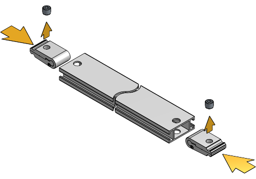

Insert the socket screw and tighten it until just before the Brace Lock starts to open up. Repeat for all Brace Profiles with holes.
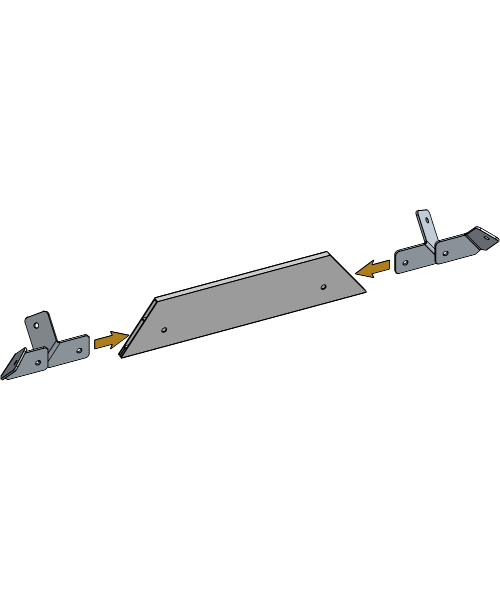
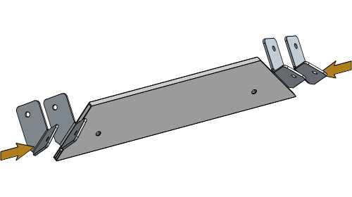
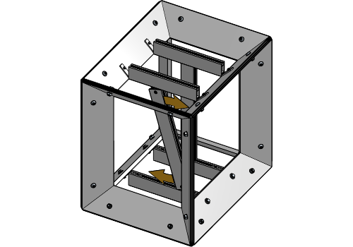
Insert all Brace Joint Plates into the bottom of a Brace Profile without holes, and slightly tighten the socket screw.
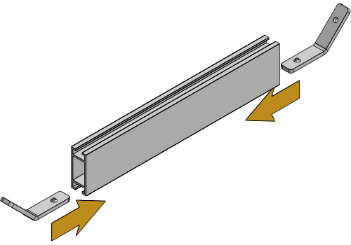
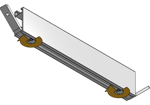
Place the Brace Joint Plate in line with the holes on the Cube PrintFrame profile.
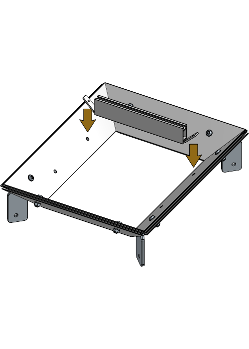
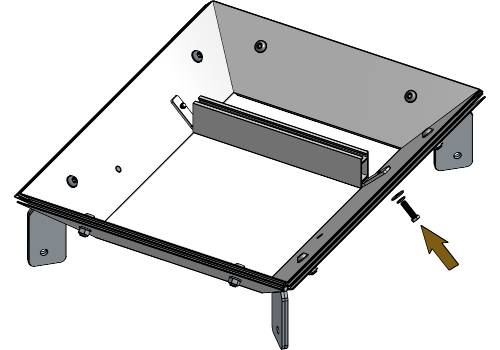
Insert the bolts with washers into the Cube Profile and tighten them slightly.
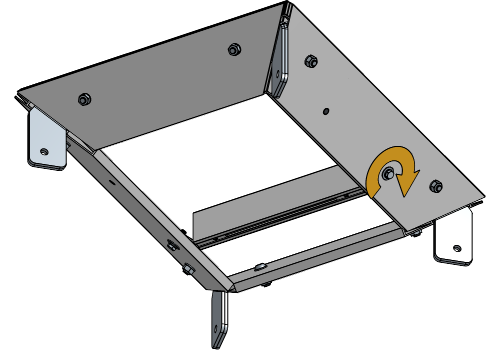
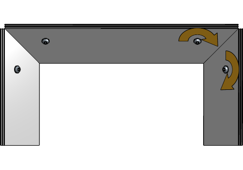
Repeat these steps for both bottom and top of the Cube Frame where holes are provided for Brace Profiles.
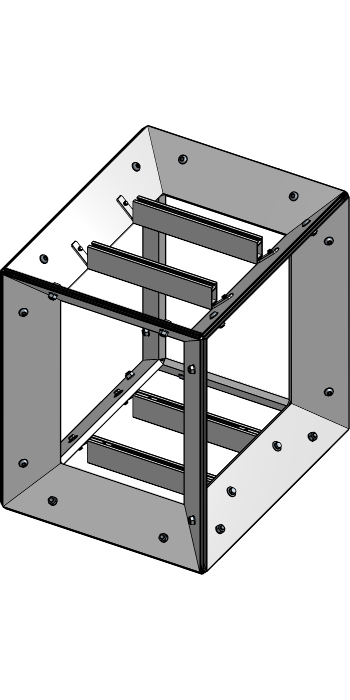
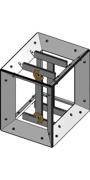
Insert the vertical Brace Profile into the Frame, positioning them in a 90° angle between the previously placed Brace Profiles.
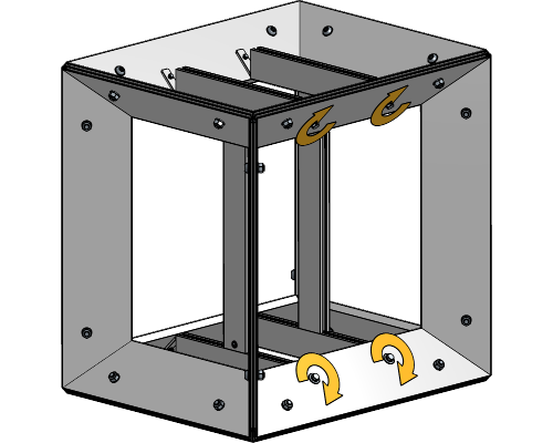
Tighten the socket screws on both sides of the Brace Profile.
Tighten all bolts at the top and bottom of the Cube PrintFrame to fully secure the Brace Profiles.
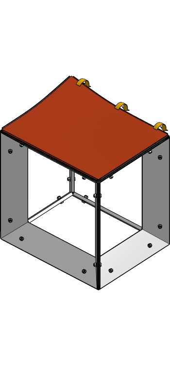
Insert the keder into the keder slot without the fabric on all sides of the frame.

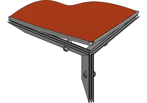
Start at the longest side of the frame, and remove the keder from the profile. Fold the fabric over the keder and insert it into the keder slot at regular intervals as work your way to the corners.
Fold the excess fabric inwards and insert the keder into the corner of the frame. Do this for both corners of the longest side.
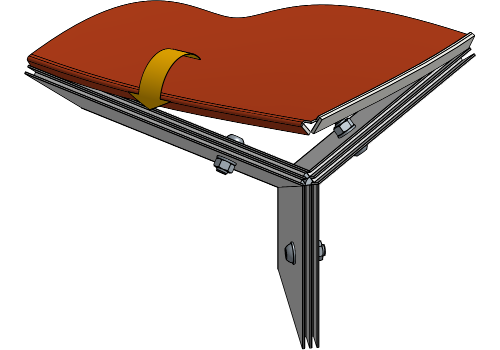
Repeat these steps for the opposite side of the frame. Start in the middle and end at the corners.
Fold the fabric over the keder, then insert it into the keder slot on both remaining sides.
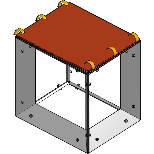
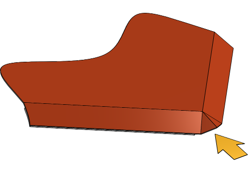
Push any remaining bumps along the profile further into the keder slot to fully secure the fabric.
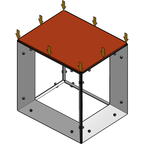
Repeat these steps for each side of the entire Cube Frame.

Your Cube PrintFrame is now completely installed and ready to be displayed!
For more technical assistance, please contact your local ShowTex
office.
The address and contact information can be found on our website:
www.showtex.com